Multi-dimensional electronic identification of articles

a multi-dimensional electronic identification and article technology, applied in the field of multi-dimensional electronic identification of articles, can solve the problems of null or dead zones in the radiation pattern, polarisation is not capable of detecting all transponders, and general null or dead zones,

Inactive Publication Date: 2005-06-21
TROLLEY SCAN
View PDF12 Cites 56 Cited by
  • Summary
  • Abstract
  • Description
  • Claims
  • Application Information

AI Technical Summary

Benefits of technology

[0026]Typically, the transponder includes a control logic circuit connected to the short term memory means, the short term memory means being responsive to a memory set signal from the control logic circuit, and the control logic means being responsive to a memory status signal from the short term memory means, the memory set signal being generated by the control logic circuit in response to the successful transmission of the identification signal, and the memory status signal being arranged to prevent the transponder, via the control logic circuit, from subsequently transmitting the identification signal for the time period.
[0027]The short term memory means may include an RC-type circuit having a predetermined time constant proportional to the time period, and comparator means having the RC-type circuit as an input and the memory status signal as an

Problems solved by technology

Invariably, the transponders are randomly oriented, with the result that a single reader with a single energy polarisation is not capable of detecting all of the transponders.
Nulls or dead zones also occur in the radiation pattern of a single reader due to interference patterns from reflecting surfaces and the like.
The problems associated with differences in polarisation and nulls or dead zones generally arise in the case of passive transponder systems, where the transponders are powered by an energising field, typically for the time period that such energising field exist

Method used


Image

  • Multi-dimensional electronic identification of articles
  • Multi-dimensional electronic identification of articles
  • Multi-dimensional electronic identification of articles

Examples


Embodiment Construction

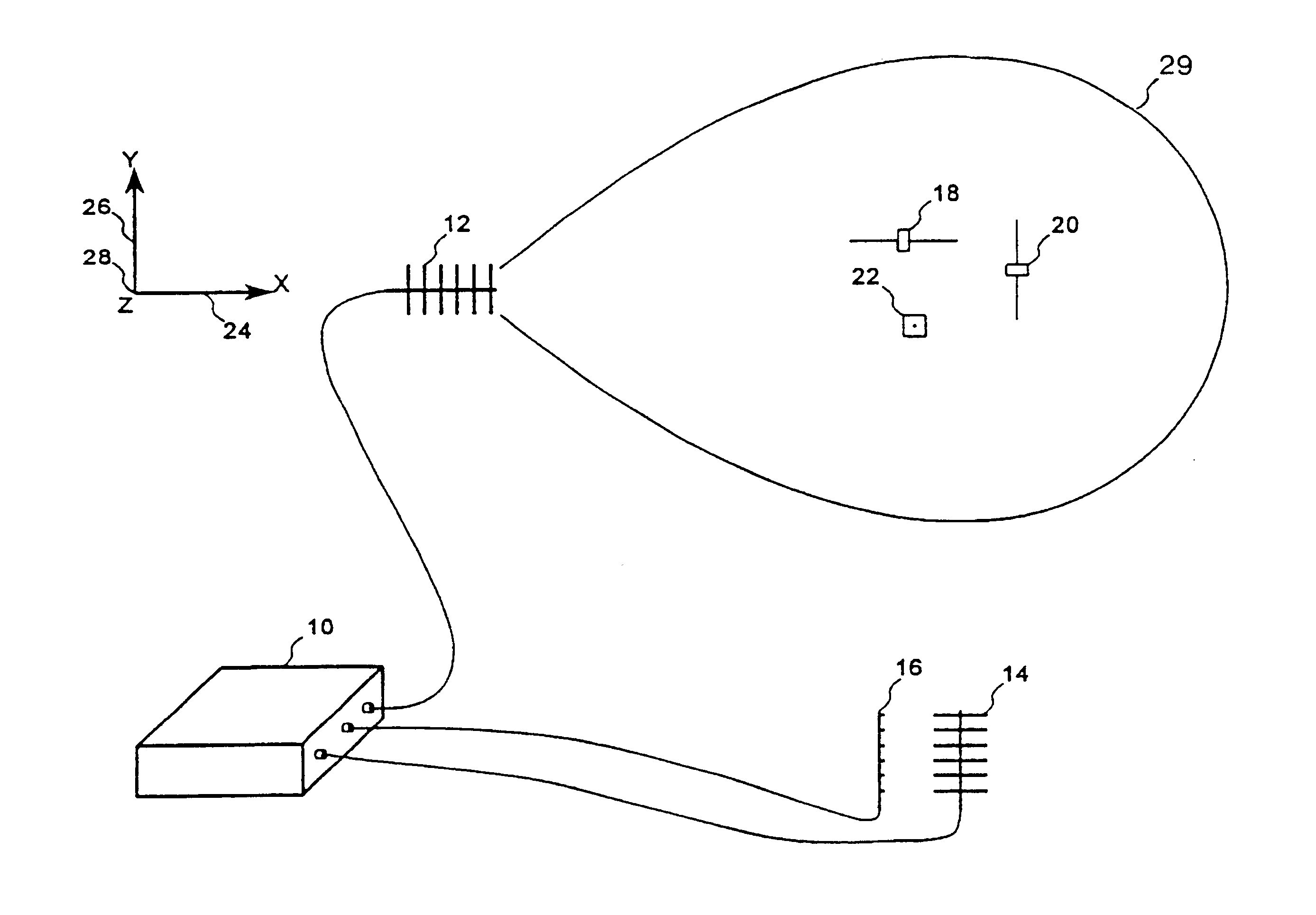
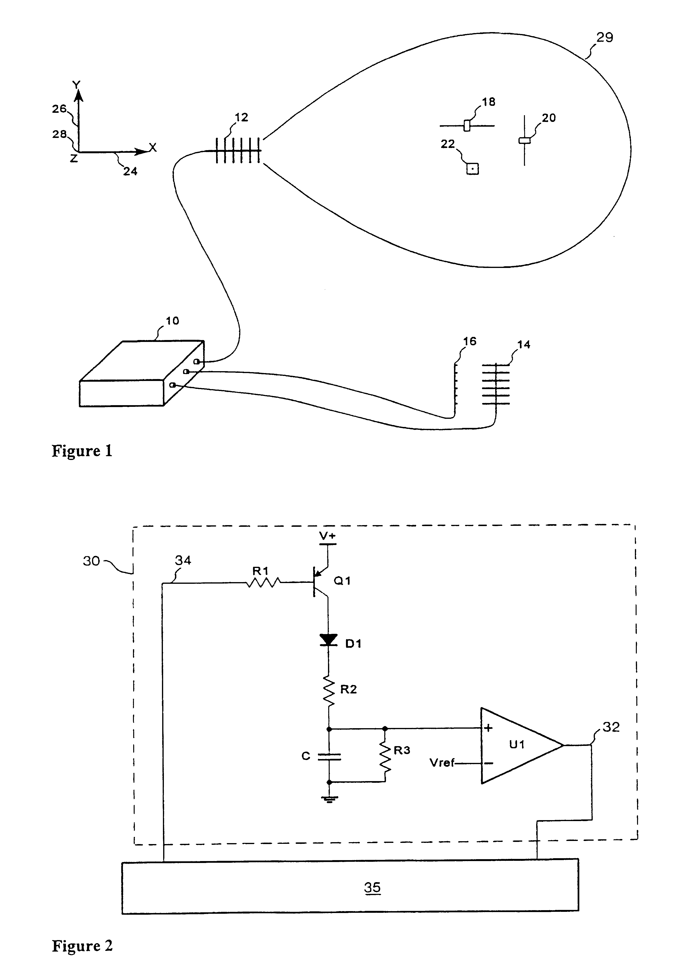
[0036]FIG. 1 shows a reader or interrogator 10 with three Yagi antennas 12, 14 and 16. The antennas are positioned so that differently oriented transponders 18, 20 and 22 are within the effective reading range or energising field of at least one of the antennas. Antenna 12 is horizontally polarised and is aligned along the x-axis 24, antenna 14 is horizontally polarised and is aligned along the y-axis 26 and antenna 16 is vertically polarised and is aligned along the y-axis 26. The z-axis 28 extends vertically into the page. Transponder 18 lies along the x-axis 24, transponder 20 along the y-axis 26 and transponder 9 along the z-axis28. The effective interrogator field or reading range of antenna 12 is depicted by an oval footprint 29. The effective reading range is defined as the range within which any transponder which has the correct antenna polarisation for reader antenna 12 will collect sufficient energy to power its circuitry. Thus transponder 18 will essentially receive energ...


PUM


Abstract

An identification system is provided for identifying a plurality of randomly aligned object-based transponders (18, 20, 22) passing through a predetermined reading volume. A reader (10) includes multiple transmitting and receiving antenna arrays (12, 14, 16) which are arranged sequentially to transmit interrogating and energizing fields (29) into the reading volume, with each energizing field having a different polarisation. Each transponder (12, 14, 16) is arranged to be powered by at least one of the interrogating and energizing fields, and includes a short term memory module (30) which is arranged to record the successful transmission or otherwise of the identification signal of the transponder (20) and to retain the record in the absence of a power supply to the transponder. The short term memory module has a retention time longer than any predicted interruption of power supply to the transponder via one of the energizing fields within the reading volume. The minimum memory retention time is typically the time period taken for the sequential transmission of all but one of the interrogating and energizing fields (29) during an interrogation cycle.

Description

BACKGROUND OF THE INVENTION[0001]THIS invention relates to the multi-dimensional electronic identification of articles.[0002]In radio frequency identification systems, a reader is typically used to read the identity of a number of objects in the form of transponders which are attached to goods to be identified, and to communicate the identification information to displays or computer networks. Communication between the reader and the transponders is by electromagnetic means, allowing transponders to be identified that are not in line of sight with the reader. Invariably, the transponders are randomly oriented, with the result that a single reader with a single energy polarisation is not capable of detecting all of the transponders. Nulls or dead zones also occur in the radiation pattern of a single reader due to interference patterns from reflecting surfaces and the like.[0003]The problems associated with differences in polarisation and nulls or dead zones generally arise in the cas...

Claims


Application Information

Patent Timeline
IPC IPC(8): G06K7/00G06K19/07G01S13/74G06K7/10G06K17/00H04B1/59
CPCG06K7/0008G06K19/0723G06K7/10039
Inventor MARSH, MICHAEL JOHN CAMILLEHODSON, TREVOR MEREDITH
Owner TROLLEY SCAN
Why Eureka
Try Eureka