Liquid crystal display viewable under all lighting conditions

a liquid crystal display and lighting condition technology, applied in non-linear optics, instruments, optics, etc., can solve the problems of excessive heat generation, increased power consumption of additional lamps, and insufficient anti-reflection coating alone to provide an lcd viewable under direct sunlight, etc., to achieve the effect of not consuming high power

Inactive Publication Date: 2005-06-21
WANG RAN HONG RAYMOND +1
View PDF5 Cites 221 Cited by
  • Summary
  • Abstract
  • Description
  • Claims
  • Application Information

AI Technical Summary

Benefits of technology

[0013]Accordingly, one object of the invention is to provide a liquid crystal display with good color, adequate brightness and sufficient contrast for outdoor applications.
[0014]A second object of the invention is to provide a liquid crystal display with good color, adequate brightness and sufficient contrast for indoor applications.
[0016]A fourth object of the invention is to provide a liquid crystal display that is viewable under direct sunlight and does not consume high power to cause excessive heat generation.
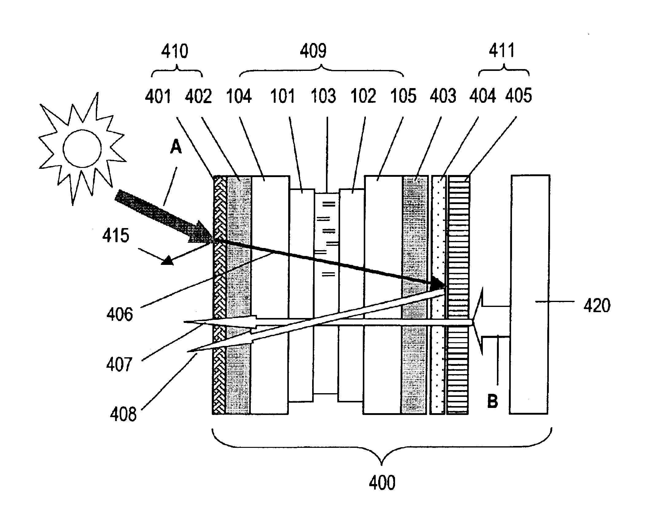
[0017]To achieve these and other advantages and in accordance with the purpose of the invention, as embodied and broadly described herein, the invention provides a liquid crystal display viewable under all lighting conditions without excessive power consumption. The LCD comprises a first dichroic polarizer, a second dichroic polarizer, an anti-reflection layer positioned in front of the first dichroic polarizer and a liquid crystal panel positioned between the first dichroic polarizer and the second dichroic polarizer. In addition, the LCD comprises a backlight assembly positioned behind the second dichroic polarizer. Finally, the LCD comprises a diffusing transflector positioned between the backlight assembly and the second dichroic polarizer. The diffusing transflector comprises a selective diffusing element and a selective transflective element.

Problems solved by technology

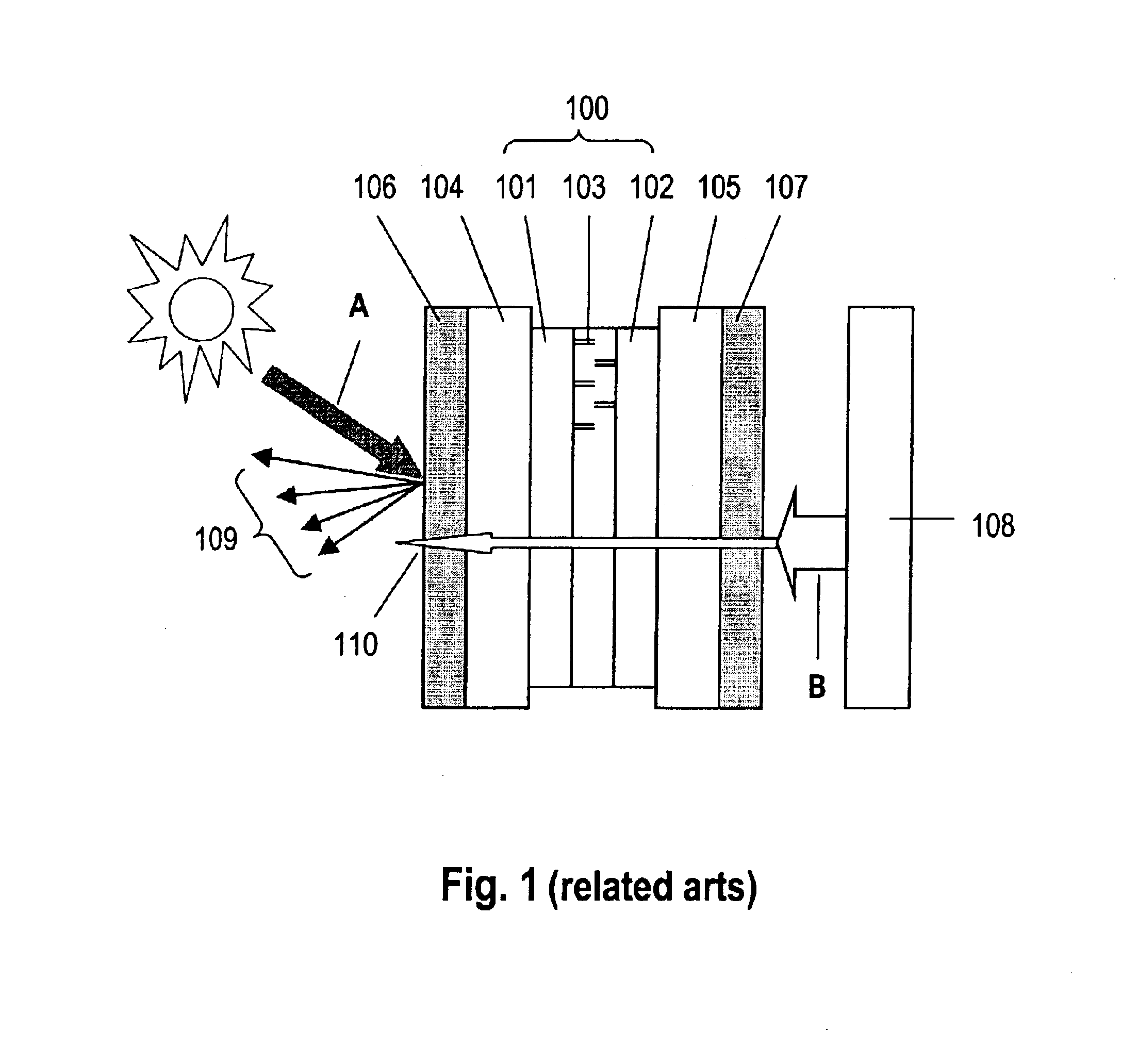
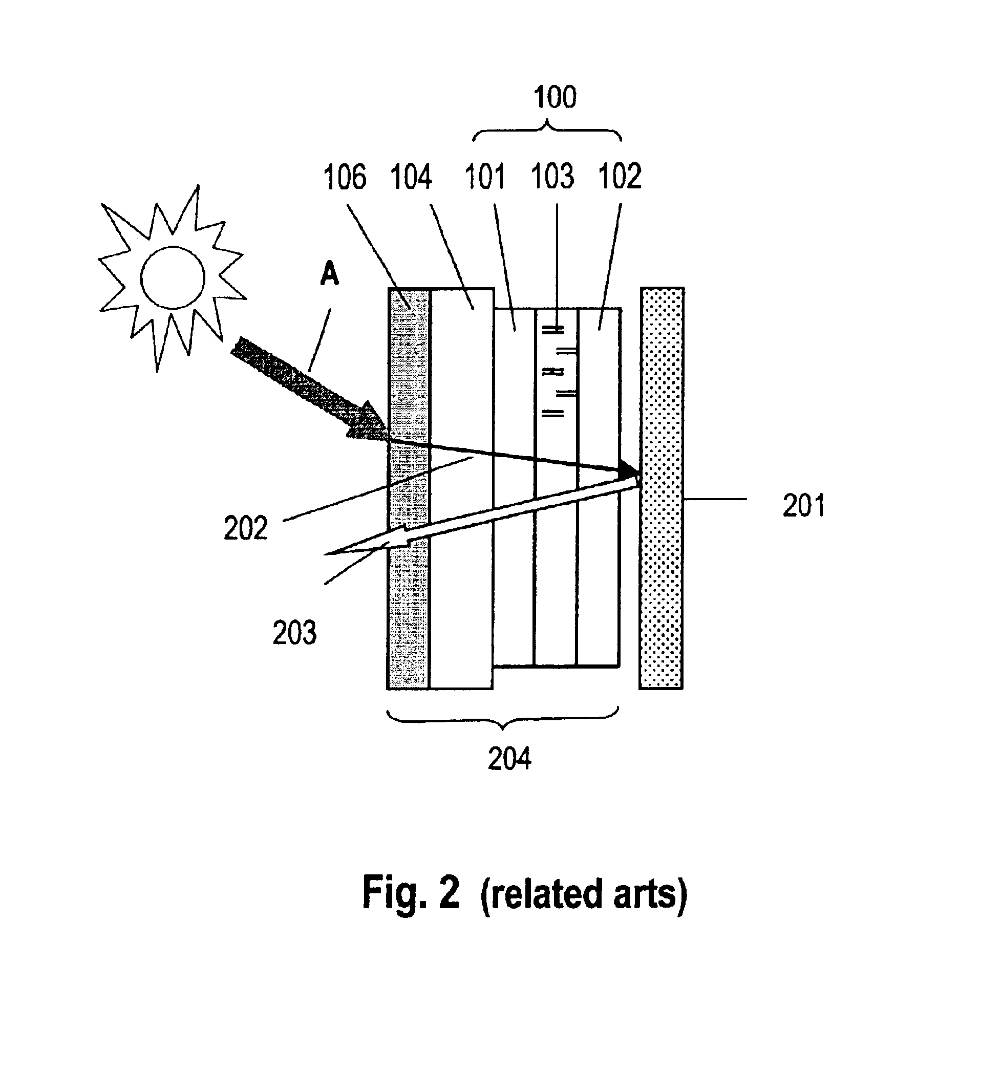
Although providing some improvement, the anti-reflection coating alone is not sufficient to provide an LCD viewable under direct sunlight.
The additional lamps consume more power, generate excessive heat, experience contrast washout and require dimension and circuit alterations.
Alterations of the LCD's dimensions and circuits are costly.
Thus, high bright LCDs generally create more problems than they solve.
However, LCD brightness diminishes as ambient light decreases.
This disadvantage of the reflective LCD strongly limits its applications.
However, the combination of reflective portions 301r and transmissive portions 301t within the same domain (pixel portions 102) imposes undesirable features on the LCD.
The problems are more noticeable when the LCD is used indoors, and include low brightness, loss of color, low contrast and a narrow viewing angle.
In addition, pixel size of the LCD is limited by the need to accommodate both transmissive and reflective electrodes.
The limited pixel size results in increased manufacturing difficulties and costs for higher resolutions.
Although easy to construct, this type of transflective LCD has inefficient illumination.
A high bright LCD, though acceptable for both indoor and outdoor applications, consumes high power and demands various complimentary re-designs of the device system to accommodate the excessive heat.
Reflective LCDs do not perform well indoors.
Transflective LCDs are limited by pixel size and do not perform optimally under certain ambient light.

Method used


Image

  • Liquid crystal display viewable under all lighting conditions
  • Liquid crystal display viewable under all lighting conditions
  • Liquid crystal display viewable under all lighting conditions

Examples


example 1

A Direct Sunlight Readable 15″ TFT LCD

[0049]Referring now to FIG. 8, a diagram of the structure of a 15″ desktop monitor Thin Film Transistor Liquid Crystal Display (TFT LCD) is shown (related art). The LCD 800 comprises a display unit 801 with a liquid crystal panel sandwiched between a pair of dichroic polarizers. The dichroic polarizers have off-axis transmission directions. The backlight cell 810 includes a diffusive reflector 805, a wave guide plate with four lamps 804, a rear diffuser 803 positioned in front of wave guide plate 804, a sheet of brightness enhancement film 802 positioned in the front side of rear diffuser 803 and a front diffuser 806 positioned in front of the brightness enhancement film 802. The TFT LCD illuminates about 250 to 275 nits. The display performs nicely indoors but visibility diminishes when the display moves outdoors. The image is totally invisible when the display is positioned towards direct sunlight.

[0050]With reference to FIG. 9, a diagram of a...

example 2

A Direct Sunlight Readable 14.2″ Notebook Computer TFT LCD

[0052]With reference to FIG. 11, a diagram of the structure of a 14.2″ notebook computer TFT LCD is shown (related art). The LCD 1100 comprises a display unit 1101 with a liquid crystal panel sandwiched between a pair of dichroic polarizers with parallel transmission directions. The backlight cell 1110 is composed of a diffusely reflector 1105, a wave guide plate coupled with one lamp 1104, a sheet of diffuser 1103 positioned on the front side of wave guide plate 1104, two sheets of brightness enhancement film 1102 positioned in the front side of diffuser 1103, and another diffuser 1106 in front of enhancement film 1102. The above described unit illuminates between 120 and 140 nits. The display performs well indoors but is very difficult to view under any outdoors conditions.

[0053]Referring now to FIG. 12, a diagram of an embodiment of the present invention modifying the 14.2″ notebook computer TFT LCD 1100 is shown. The tran...

example 3

A Direct Sunlight Readable 10.4″ Tablet TFT LCD

[0054]With reference to FIG. 13, a diagram of the structure of a 10.4″ Tablet TFT LCD is shown (related art). The LCD 1300 comprises a display unit 1301 with a liquid crystal panel sandwiched between a pair of dichroic polarizers with parallel transmission directions. The backlight cell 1310 is composed of a diffusive reflector 1305, a wave guide plate coupled with one edge lamp 1304, a sheet of diffuser 1303 positioned in the front side of wave guide plate 1304, a sheet of brightness enhancement film 1302 positioned in front of diffuser 1303, and a reflective polarizer 1306 in front of enhancement film 1302. The above described unit illuminates approximately 200 nits. The display gives good optical performances indoors, yet is very difficult to view under any outdoor conditions.

[0055]With reference to FIG. 14, a diagram of an embodiment of the present invention modifying the 10.4″ Tablet TFT LCD 1300 is shown. The transflective TFT LCD...


PUM

PropertyMeasurementUnit
hazeaaaaaaaaaa
hazeaaaaaaaaaa
hazeaaaaaaaaaa

Abstract

A liquid crystal display (LCD) viewable under all lighting conditions without excessive power consumption is described. The LCD comprises a first dichroic polarizer, a second dichroic polarizer, an anti-reflection layer positioned in front of the first dichroic polarizer and a liquid crystal cell positioned between the first dichroic polarizer and the second dichroic polarizer. In addition, the LCD comprises a backlight assembly positioned behind the second dichroic polarizer. Finally, the LCD comprises a diffusing transflector positioned between the backlight assembly and the second dichroic polarizer. The diffusing transflector comprises a diffusing element and a transflective element.

Description

BACKGROUND OF THE INVENTION[0001]1. Field of the Invention[0002]This invention relates to a liquid crystal display device, and more particularly, to an improved transflective liquid crystal display viewable under all lighting conditions, such as total dark, indoor lighting, in shade, medium sunlight, strong sunlight, and direct sunlight, without excessive power consumption.[0003]2. Description of the Related Art[0004]Many features of liquid crystal displays (LCDs), such as light weight and size, low power consumption and high resolution, make LCDs a popular choice in various electronic applications. These applications include digital cameras, palm PCs, notebook computers, tablet PCs, workstations, and navigation systems in automobiles, marine vessels, and airplanes. Most of these applications are portable and can be transited between indoor and outdoor. Thus, there is a need to develop a display to accommodate both indoor and outdoor environments and perform regardless of different ...

Claims


Application Information

Patent Timeline
Patent Type & Authority Patents(United States)
IPC IPC(8): G02F1/1335G02F1/13
CPCG02F1/133502G02F1/133555G02F1/133504G02F1/133536
Inventor WANG, RAN-HONG RAYMONDWANG, MIN-SHINE C.
Owner WANG RAN HONG RAYMOND
Why Eureka
Try Eureka