
Magnetic transfer method and magnetic transfer device

a magnetic transfer and master carrier technology, applied in the field of magnetic transfer methods and magnetic transfer devices, can solve the problems of pattern breakage and master carrier deformation, and achieve the effect of favorable magnetization pattern, and suppressing master carrier deformation and pattern breakag

Inactive Publication Date: 2005-06-21
FUJIFILM CORP +1
View PDF4 Cites 0 Cited by
  • Summary
  • Abstract
  • Description
  • Claims
  • Application Information

AI Technical Summary

Benefits of technology

[0012]In light of the above-described circumstances, an object of the present invention is to provide a magnetic transfer method and a magnetic transfer device which enable magnetic transfer to be performed onto more slave media using one magnetic transfer master carrier and in which favorable transferred signals can be obtained in slave media after the magnetic transfer.
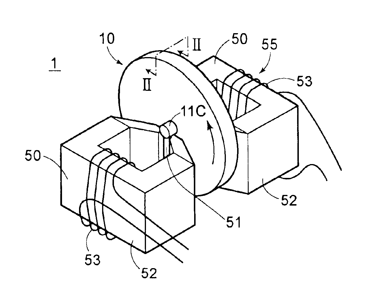
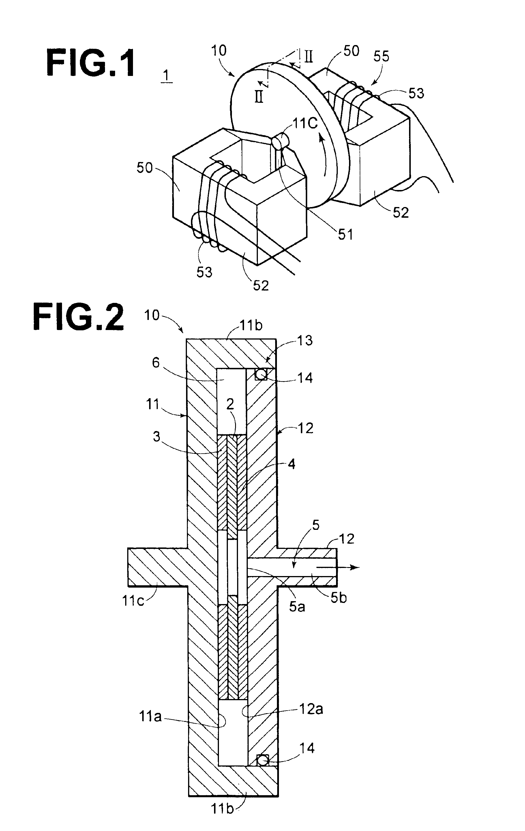
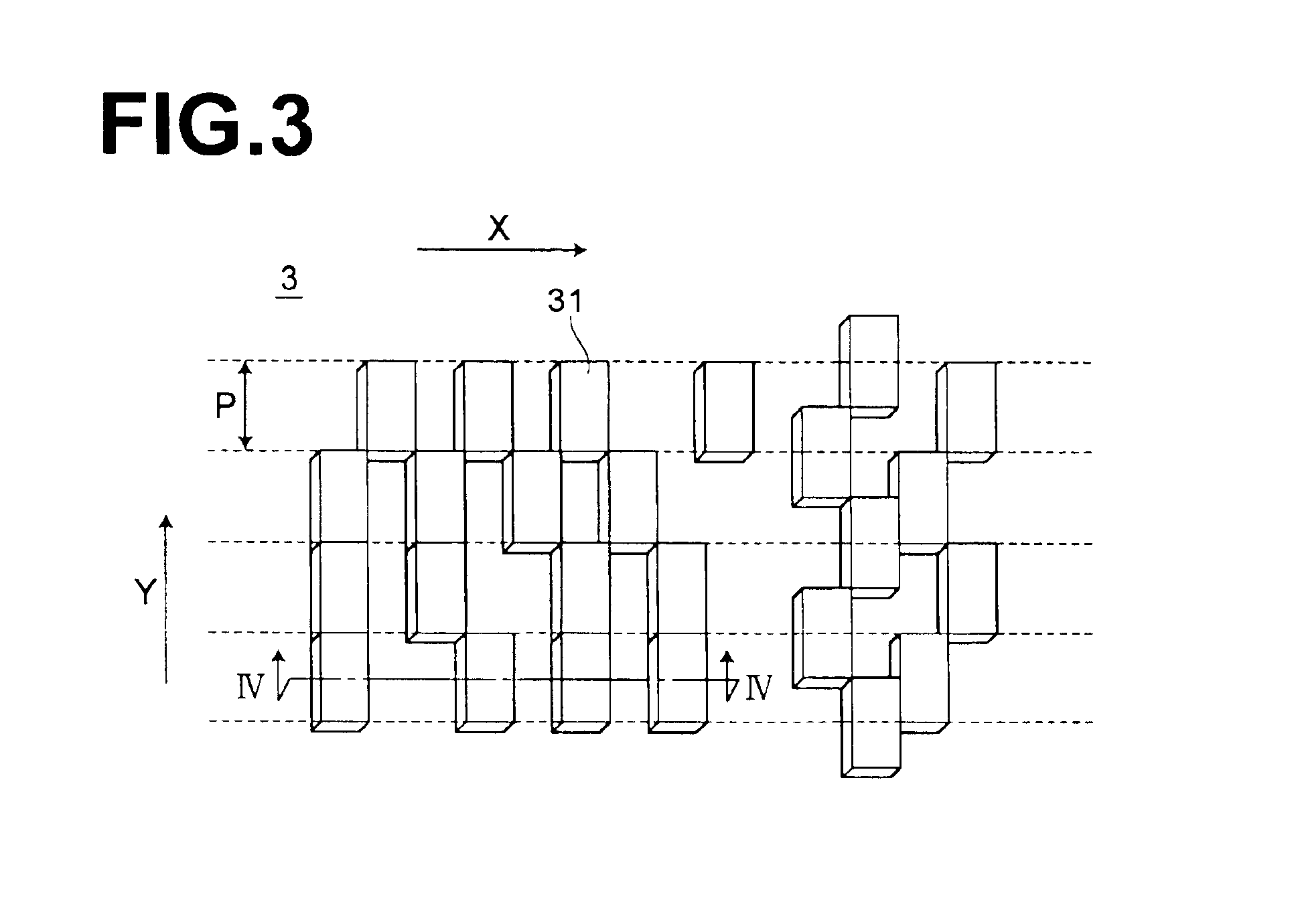
[0029]In a magnetic transfer method of the present invention, a master carrier including a substrate having a Young's modulus E (GPa) of 85 to 250 is used, and an expression 2≦αEd3 / {P(S2 / S1)}≦400 (where the constant α=7.37×10⁹) is satisfied, where d (m) is a thickness of the substrate of the master carrier from a bottom face of a recessed portion to a back face, S1 (m2) is a total area of cross sections of projected portions which are parallel to a plane of the substrate at a height of 50% of Dmax from the bottom face of the recessed portion when a height from the bottom face of the recessed portion to a top face of a projected portion is denoted by Dmax, S2 (m2) is a total area of bottom faces of recessed portions and cross sections of the projected portions at a position of the relevant bottom faces, and P is a tight contact pressure between the master carrier and a recording medium. Accordingly, the master carrier and the recording medium can be uniformly brought into tight contact with each other over the entire surfaces, and the deformation of the master carrier and pattern breakage can be suppressed.
[0030]A magnetic transfer device of the present invention is equipped with a master carrier including a substrate having a Young's modulus E (GPa) of 85 to250. In the magnetic transfer device of the present invention, an expression 2≦αEd3 / {P(S2 / S1)}≦400 (where the constant α=7.37×10⁹) is satisfied, where d (m) is a thickness of the substrate of the master carrier from a bottom face of a recessed portion to a back face, S1 (m2) is a total area of cross sections of projected portions which are parallel to a plane of the substrate at a height of 50% of Dmax from the bottom face of the recessed portion when a height from the bottom face of the recessed portion to a top face of a projected portion is denoted by Dmax, S2 (m2) is a total area of bottom faces of recessed portions and cross sections of the projected portions at a position of the relevant bottom faces, and P is a tight contact pressure between the master carrier and a recording medium by the tight contact means. Accordingly, the master carrier and the recording medium can be uniformly brought into tight contact with each other over the entire surfaces, and the deformation of the master carrier and pattern breakage can be suppressed.
[0031]The present inventors have found the following fact: in the case where αEd3 / {P(S2 / S1)} is smaller than 2, there is a problem that a local tight contact pressure between a master carrier and a slave medium becomes too large and that pattern breakage tends to occur; in the case where αEd3 / {P(S2 / S1)} is larger than 400, there is a problem that the tight contact between them is insufficient and that uniform signal transfer over the entire surfaces is not performed. Meanwhile, the present inventors have found the following fact: in the case where 2≦αEd3 / {P(S2 / S1)}≦400, a favorable magnetization pattern can be formed on the recording medium because the master carrier and the recording medium can be uniformly brought into tight contact with each other over the entire surfaces, and magnetic transfer to more recording media can be performed by the same master carrier than heretofore to improve a yield because the deformation of the master carrier and pattern breakage can be suppressed.
[0032]Thus, reproduced signals of high quality can be obtained from a recording medium in which a favorable magnetization pattern is formed. Moreover, due to the improvement in a yield, a recording medium having a high signal quality can be inexpensively provided.
[0033]Note that, in the magnetic transfer device of the present invention, the durability of the master carrier when pressure is applied can be improved and transfer quality can be improved by adopting, as the substrate of the magnetic transfer master carrier, one which has S1S2 in the range of 2 to 100 and a thickness d in the range of 0.05 to 0.71 mm and / or which is made of Ni or Ni alloy.

Problems solved by technology

Meanwhile, according to research by the present inventors, it has become clear that the deformation of the master carrier and pattern breakage tend to occur as this tight contact pressure increases.

Method used


Image

  • Magnetic transfer method and magnetic transfer device
  • Magnetic transfer method and magnetic transfer device
  • Magnetic transfer method and magnetic transfer device

Examples


examples

[0073]Next, the results of performing magnetic transfer by use of magnetic transfer devices and methods of examples and comparative examples of the present invention and evaluating the quality of transferred signals and the durability of master carriers will be described. In the magnetic transfer devices of Examples 1 to 8 and Comparative Examples 1 to 3, conditions including the elastic modulus and dimensions of a master carrier, the tight contact pressure between a master carrier and a slave medium are different from each other.

[0074]The master carrier of the magnetic transfer device of Example 1 includes as a substrate a disk-shaped Ni substrate prepared using a method of preparing a stamper. In the Ni substrate, projected / recessed pattern signals in which the track width was 0.3 μm, the bit length was 0.15 μm at a position of 20 mm in the radial direction, i.e., at the innermost circumference, and the height of a projected portion (depth of a groove in a recessed portion) was 0....


PUM


Abstract

In a magnetic transfer master carrier, as a substrate, one having a Young's modulus E (GPa) in the range of 85 to 250 is used. Magnetic transfer is performed under conditions in which 2≦αEd3 / {P(S2 / S1)}≦400 (where the constant α=7.37×10⁹) is satisfied, where d (m) is the thickness of the substrate from the bottom face of a recessed portion to the back face, S1 (m2) is the total area of the cross sections of the projected portions which are parallel to the plane of the substrate at a height of 50% of Dmax from the bottom face of the recessed portion when the height from the bottom face of the recessed portion to the top face of a projected portion is denoted by Dmax, S2 (m2) is the total area of the bottom faces of the recessed portions and the cross sections of the projected portions at the positions of the relevant bottom faces, and P (MPa) is the tight contact pressure between the master carrier and the slave medium at the time of magnetic transfer.

Description

BACKGROUND OF THE INVENTION[0001]1. Field of the Invention[0002]The present invention relates to a magnetic transfer method in which a magnetic transfer master carrier having pattern-shaped projections and recesses for transferring information to a magnetic recording medium is used, and a magnetic transfer device equipped with the magnetic transfer master carrier.[0003]2. Description of the Related Art[0004]In general, with the increase in information content, inexpensive media having a large-capacity for recording a large amount of information and preferably providing so-called quick access capable of reading a required point within a short time are desired with regard to a magnetic recording medium. For example, high-density magnetic recording media which are flexible disks such as hard disks or ZIPs (Iomega Corporation) have been known. In these high-density magnetic recording media, information recording areas are constituted of narrow tracks. In order to accurately scan a narro...

Claims


Application Information

Patent Timeline
IPC IPC(8): G11B5/86G11B17/00G11B5/82G11B5/73
CPCB82Y10/00G11B5/743G11B5/865G11B17/00G11B5/82
Inventor NISHIKAWA, MASAKAZU
Owner FUJIFILM CORP
Learn More