Image forming apparatus including plural conveyor units with conveyance path length/conveyance speed relationships

a technology of image forming apparatus and conveyor unit, which is applied in the direction of electrographic process apparatus, thin material handling, instruments, etc., can solve the problems of reducing the fixing speed, deteriorating image forming efficiency, and widened sheet spacing, so as to shorten the image forming time period of the first sheet without deteriorating image quality. , to achieve the effect of improving image forming efficiency

Inactive Publication Date: 2005-06-21
CANON KK
View PDF4 Cites 8 Cited by
  • Summary
  • Abstract
  • Description
  • Claims
  • Application Information

AI Technical Summary

Benefits of technology

[0023]The present invention has an object to improve an image forming efficiency and to shorten the image forming time period of a fir

Problems solved by technology

In short, in the aforementioned control, the image forming efficiency is deteriorated for the causes that the fixing speed is lowered and that the sheet spacing is widened.
Especially in the case of an intermediate transfer type copying machine, the extremely elongation of the distance from the first image formation unit to the transfer unit raises a serious problem.
In addition, the latent image may diffuse

Method used


Image

  • Image forming apparatus including plural conveyor units with conveyance path length/conveyance speed relationships
  • Image forming apparatus including plural conveyor units with conveyance path length/conveyance speed relationships
  • Image forming apparatus including plural conveyor units with conveyance path length/conveyance speed relationships

Examples


first embodiment

[0050](First Embodiment)

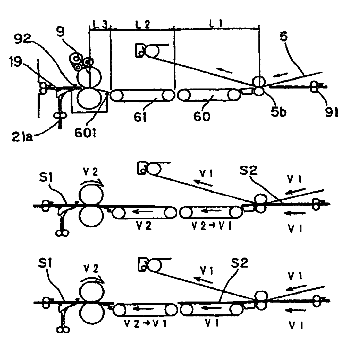
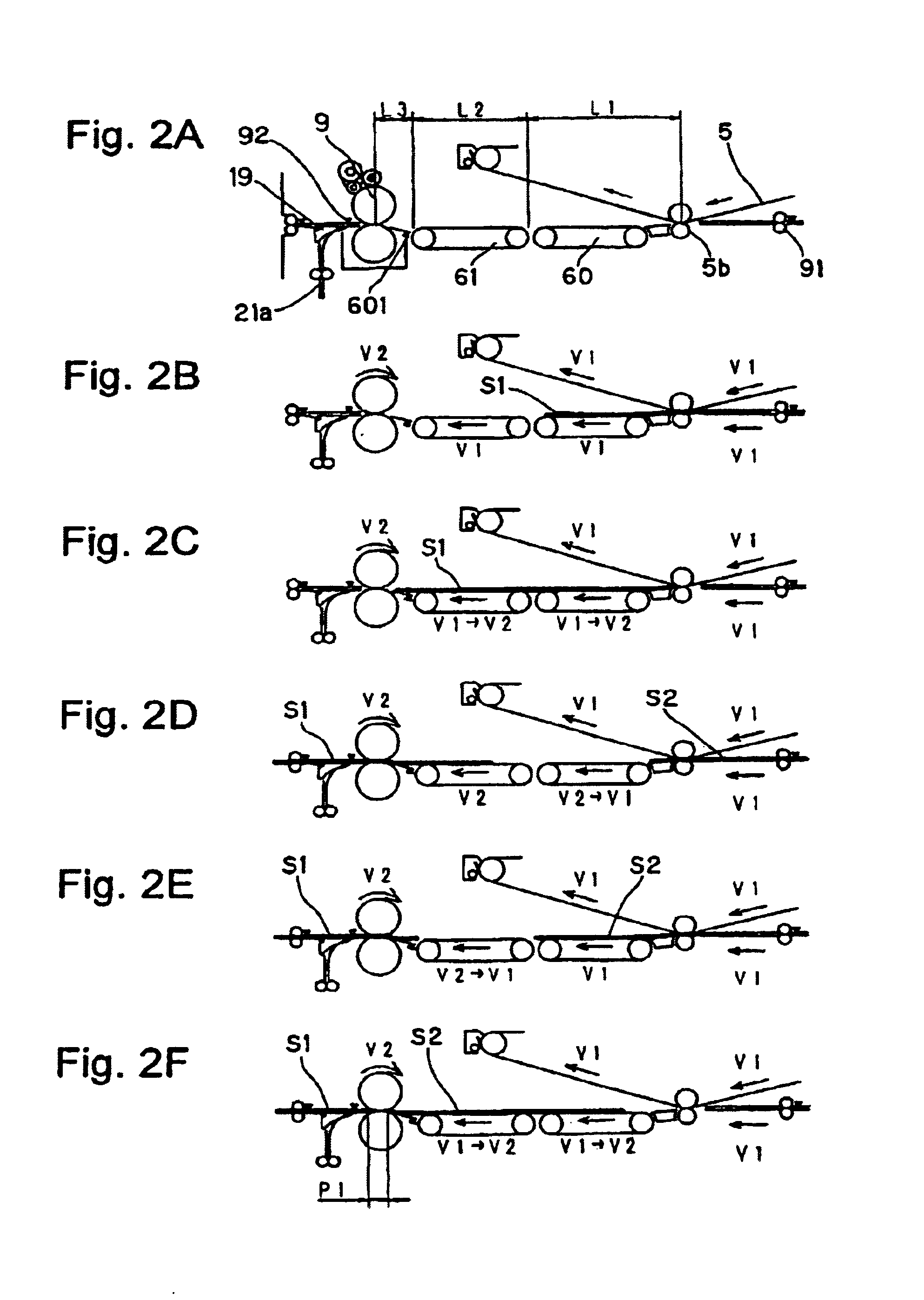
[0051]A first embodiment will be described with reference to FIG. 1 to FIG. 5.

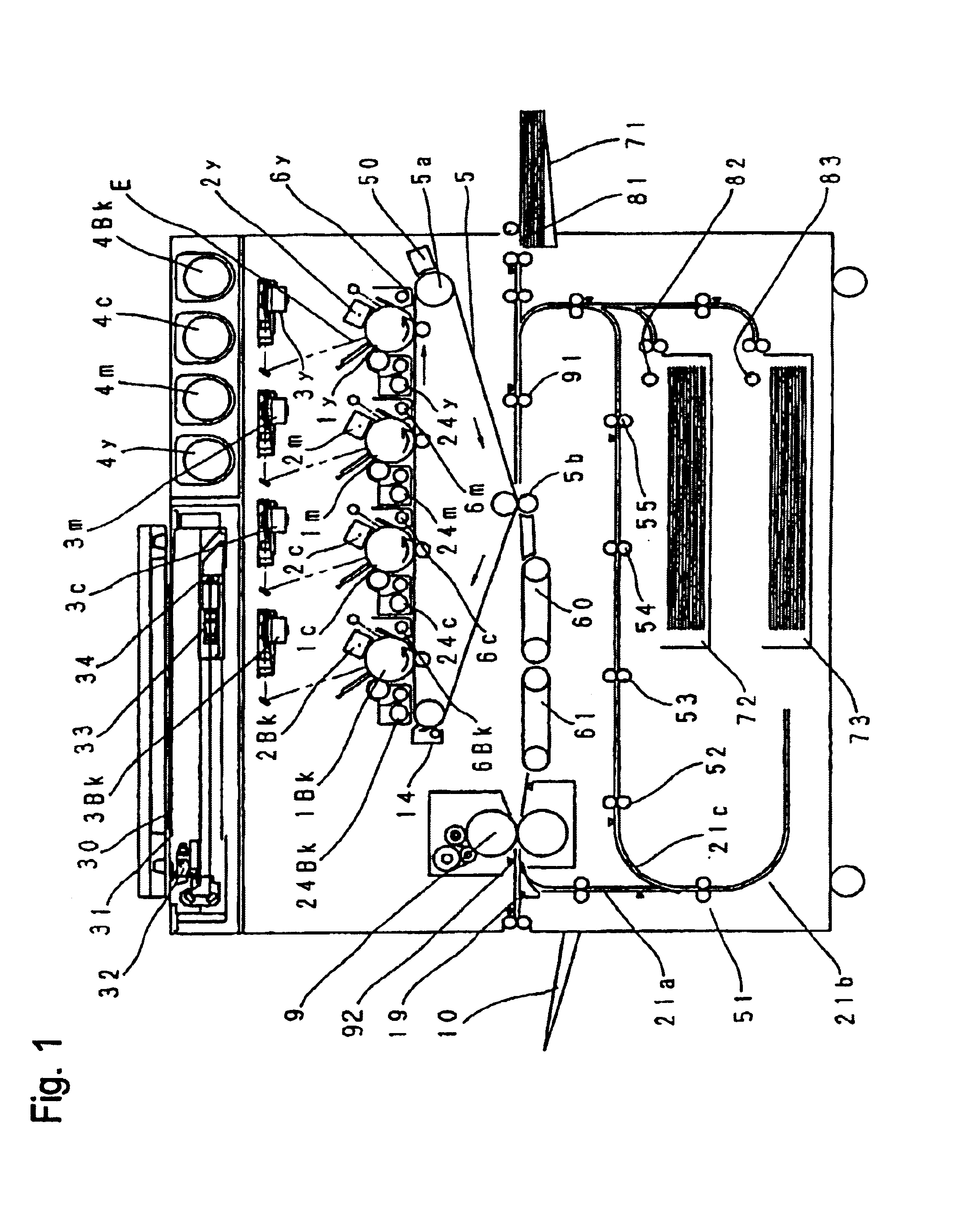
[0052]The first embodiment of the invention will be described in detail with reference to the accompanying drawings. FIG. 1 presents a schematic sectional view of a full-color image forming apparatus according to the first embodiment.

[0053]The apparatus of FIG. 1 is a copying machine, which is provided with a digital color image reader and a toner container at its upper portion and a digital color image printer at its lower portion. This copying machine is of an intermediate transfer type having four image formation units.

[0054]In the reader, a document 30 is placed on a document glass plate 31 and is scanned while being exposed by an exposure lamp 32. An optical image reflected from the document 30 is focused by a lens 33 into a full-color CCD sensor 34 to produce a color-separated image signal.

[0055]This color-separated image signal is processed through an amplifier circuit by a v...

second embodiment

[0126](Second Embodiment)

[0127]A second embodiment of the invention will be described with reference to FIG. 6. The copying machine of this construction is not the intermediate transfer type unlike the first embodiment but the type, in which the toner is transferred directly to the sheet from the photosensitive drum acting as the image bearing member.

[0128]The remaining constructional members such as the reader are identical in construction and function to the copying machine of the first embodiment. The sheet passes through the four image formation units while being electrostatically adsorbed by the transfer belt 5 and is conveyed with the toner transferred thereto.

[0129]Here, the construction of the pre-fix conveyor portion may be identical to that of the first embodiment, if it is considered that the start point of the distance L1 is located not at the transfer unit of the fourth station, i.e., at the position of the transfer point 5Bk, through which the sheet trailing end passes...


PUM


Abstract

In case a fixing speed is lower than a transferring speed, the individual conveyor units are controlled such that, while a downstream conveyor unit (61) is conveying a sheet (S1) being fixed at the same speed (V2) as the fixing speed, an upstream conveyor unit (60) may convey the succeeding sheet (S2) at the same speed (V1) as the transferring speed. As a result, the spacing of the two sheets in a fixing unit (9) can be sufficiently narrowed to improve the image forming efficiency. Moreover, the transferring speed need not be decelerated according to the fixing speed. It is, therefore, possible to prevent the deterioration in the image quality and to shorten the image forming time period of the first sheet.

Description

BACKGROUND OF THE INVENTION[0001]1. Field of the Invention[0002]The present invention relates to an electrophotographic image forming apparatus such as a copying machine, a facsimile or a printer and, more particularly, to an image forming apparatus capable of switching a fixing speed in accordance with the kind of a sheet.[0003]2. Description of the Related Art[0004]In the field of the image forming apparatus such as the copying machine, the market of recent years demand the apparatus for matching various materials such as cardboard or coated paper, and the current situation is that many products can match.[0005]Generally, more calories than that for the plain paper are required for fixing an image to a sheet having a basis weight of 300 g / m2, such as “cardboard” or “super cardboard”.[0006]In case the coated paper has a large basis weight, moreover, more calories than that for the plain paper are also required not only for the coated paper but also for the sheet of a high gloss, wh...

Claims


Application Information

Patent Timeline
IPC IPC(8): G03G15/20G03G15/16G03G21/14B65H5/02G03G15/00
CPCG03G15/16G03G15/657G03G15/20
Inventor TANAKA, AKINORI
Owner CANON KK
Why Eureka
Try Eureka