Safety communication on a single backplane

a safety communication and backplane technology, applied in the field of industrial controllers, can solve problems such as the increase in the availability of the network

Inactive Publication Date: 2005-06-21
ROCKWELL AUTOMATION TECH
View PDF6 Cites 74 Cited by
  • Summary
  • Abstract
  • Description
  • Claims
  • Application Information

AI Technical Summary

Benefits of technology

The patent text describes a way to create a safe system using a standard network or backplane. This system can detect errors using different protocols that can be traded off to achieve the desired level of error detection. The technical effect of this invention is to provide a flexible and effective way to ensure safety in a networked environment.

Problems solved by technology

The present invention relates to high-reliability industrial controllers that can be used in safety systems. The problem is that current safety systems are hard-wired and expensive, while standard network protocols used in industrial control are not reliable enough for safety systems. The invention proposes a solution that allows for the use of standard networks and hardware, while also providing a safety network protocol that ensures reliable data transmission and flexible reconfiguration without the need for actual rewiring of the safety system.

Method used


Image

  • Safety communication on a single backplane
  • Safety communication on a single backplane
  • Safety communication on a single backplane

Examples


Embodiment Construction

[0040]The present invention can be part of a “safety system” used to protect human life and limb in the industrial environment. Nevertheless, the term “safety” as used herein is not a representation that the present invention will make an industrial process safe or that other systems will produce unsafe operation. Safety in an industrial process depends on a wide variety of factors outside of the scope of the present invention including: design of the safety system, installation, and maintenance of the components of the safety system, and the cooperation and training of individuals using the safety system. Although the present invention is intended to be highly reliable, all physical systems are susceptible to failure and provision must be made for such failure.

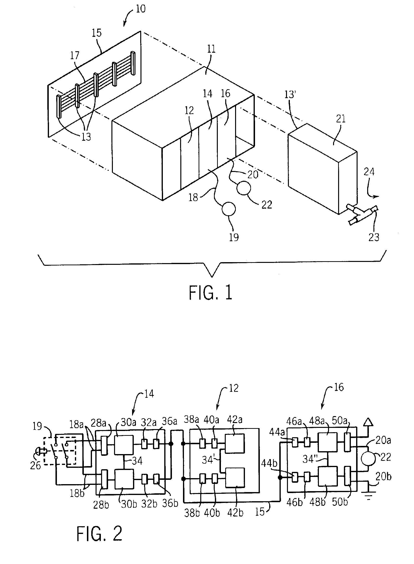
[0041]Referring now to FIG. 1, an industrial control system 10 for implementing a safety system with the present invention includes a chassis 11 holding a controller module 12 communicating on a backplane 15 of the chassis 11...


PUM


Abstract

Safety level error detection comparable to that provided by redundant wired safety relays is obtained on a backplane of a programmable logic controller or the like by a combination of error detection methods that in sum provide the requisite level of error detection required without necessitating a particular hardware requirement or duplicative message transmissions.

Description


Claims


Application Information

Patent Timeline
Owner ROCKWELL AUTOMATION TECH
Why Eureka
Try Eureka