Energy-saving optimized control system and method for refrigerator room

A refrigeration room, optimized control technology, applied in heating and ventilation control systems, heating and ventilation safety systems, heating methods, etc., can solve the problems of reducing the effect of energy consumption control, optimizing energy consumption models, and not building cooling towers at the same time

Active Publication Date: 2011-02-09
WELDTECH TECH SHANGHAI
View PDF8 Cites 69 Cited by
  • Summary
  • Abstract
  • Description
  • Claims
  • Application Information

AI Technical Summary

Problems solved by technology

[0005] In the existing technology, some methods may be feasible under stable laboratory conditions, but in the actual operation process, since all the equipment in the refrigeration room is in continuous operation, the cooling load and weather parameters will also change at any time, which will As a result, the actual values ​​of the collected parameters are not regular. Adjusting the energy consumption model through the above method cannot optimize the energy consumption model, and may even produce the opposite effect. Therefore, in actual operation, the above method is used to find the highest operating efficiency of the entire refrigeration room equipment operating point is unrealistic
In addition, in the prior art, the cooling tower heat transfer model is not established at the same time, which will inevitably reduce the effect of its energy consumption control

Method used


Image

  • Energy-saving optimized control system and method for refrigerator room
  • Energy-saving optimized control system and method for refrigerator room
  • Energy-saving optimized control system and method for refrigerator room

Examples


Embodiment Construction

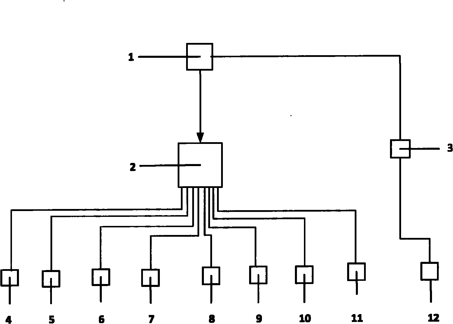
[0078] like figure 1 , figure 2 As shown, the embodiment of the device of the present invention includes: industrial control computer 1, programmable controller 2, RS485 communication interface module 3, flow sensor 4, temperature sensor 5, outdoor temperature and humidity sensor 6, three-phase active power transmitter 7, Differential pressure sensor 8, water pump inverter 9, cooling tower fan inverter 10, electric valve and switch actuator 11, chiller 12.

[0079] According to the present invention, several flow sensors 4, several temperature sensors 5, one outdoor temperature and humidity sensor 6, several three-phase active power transmitters 7, differential pressure sensors 8, several water pump frequency converters 9 and several The cooling tower fan frequency converter 10 is respectively connected with the programmable controller 2, the programmable controller 2 communicates with the industrial control computer 1 through the industrial Ethernet, and the RS485 communica...


PUM


Abstract

The invention relates to an energy-saving optimized control system and an energy-saving optimized control method for a refrigerator room. The energy-saving optimized control system comprises an industrial control computer, a flow sensor, a temperature sensor, an outdoor temperature and humidity sensor, a three-phase active power transmitter, a water pump frequency converter and a cooling tower fan frequency converter which are connected with a programmable logic controller respectively, wherein the programmable logic controller communicates with the industrial control computer through an industrial Ethernet; and an RS485 communication interface module is connected with a water cooling unit and communicates with the industrial control computer through a ModBus protocol. A mathematical model of relationships between the energy consumption and running parameters of each equipment in the refrigerator room is established to regulate the running state of each equipment in combination with real-time refrigeration loads and weather parameters, thereby fulfilling the aim of making the lowest running energy consumption of the whole refrigerator room at the premise of meeting the refrigeration loads.

Description

Technical field: [0001] The invention relates to an energy-saving system and method, in particular to a refrigeration machine room system. Background technique: [0002] In the energy consumption of the entire building, the energy consumption of the air conditioning system occupies a large proportion, generally around 40-50%. In the energy consumption of the air conditioning system, the refrigeration room equipment (including chillers, chilled water pumps, cooling water pumps and cooling towers) accounts for about 60% to 70%. In an office building using electric cooling, the annual electricity consumption of the air-conditioning cold source (refrigeration room)-chillers, freezing and cooling water pumps, and cooling towers accounts for 30-35% of the annual electricity consumption of the entire building. [0003] The cooling operation process in the air conditioning system is: the chiller prepares chilled water at a certain temperature, sends it to the terminal equipment thr...

Claims


Application Information

Patent Timeline
Patent Type & Authority Applications(China)
IPC IPC(8): F24F11/02F24F11/00
Inventor 王豪源吴刚
Owner WELDTECH TECH SHANGHAI
Why Eureka
Try Eureka