Accelerometer configuration

a technology of accelerometer and configuration, which is applied in the direction of navigation instruments, liquid fuel engine components, and vehicle registration/indication, etc., and can solve the problem that all of these requirements are necessarily a maintenance burden

Inactive Publication Date: 2005-06-21
GENERAL ELECTRIC CO
View PDF13 Cites 64 Cited by
  • Summary
  • Abstract
  • Description
  • Claims
  • Application Information

AI Technical Summary

Benefits of technology

[0006]A system and method are proposed for eliminating the need for the alternate accelerometer. This improved accelerometer configuration uses the original external accelerometer as a backup accelerometer to the fan i

Problems solved by technology

All of these requirements are n

Method used


Image

  • Accelerometer configuration
  • Accelerometer configuration

Examples


Embodiment Construction

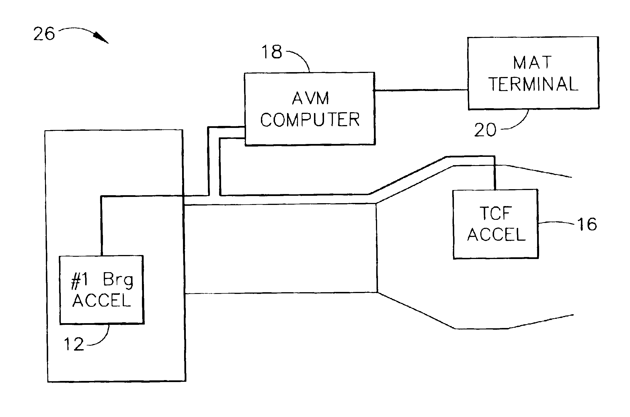
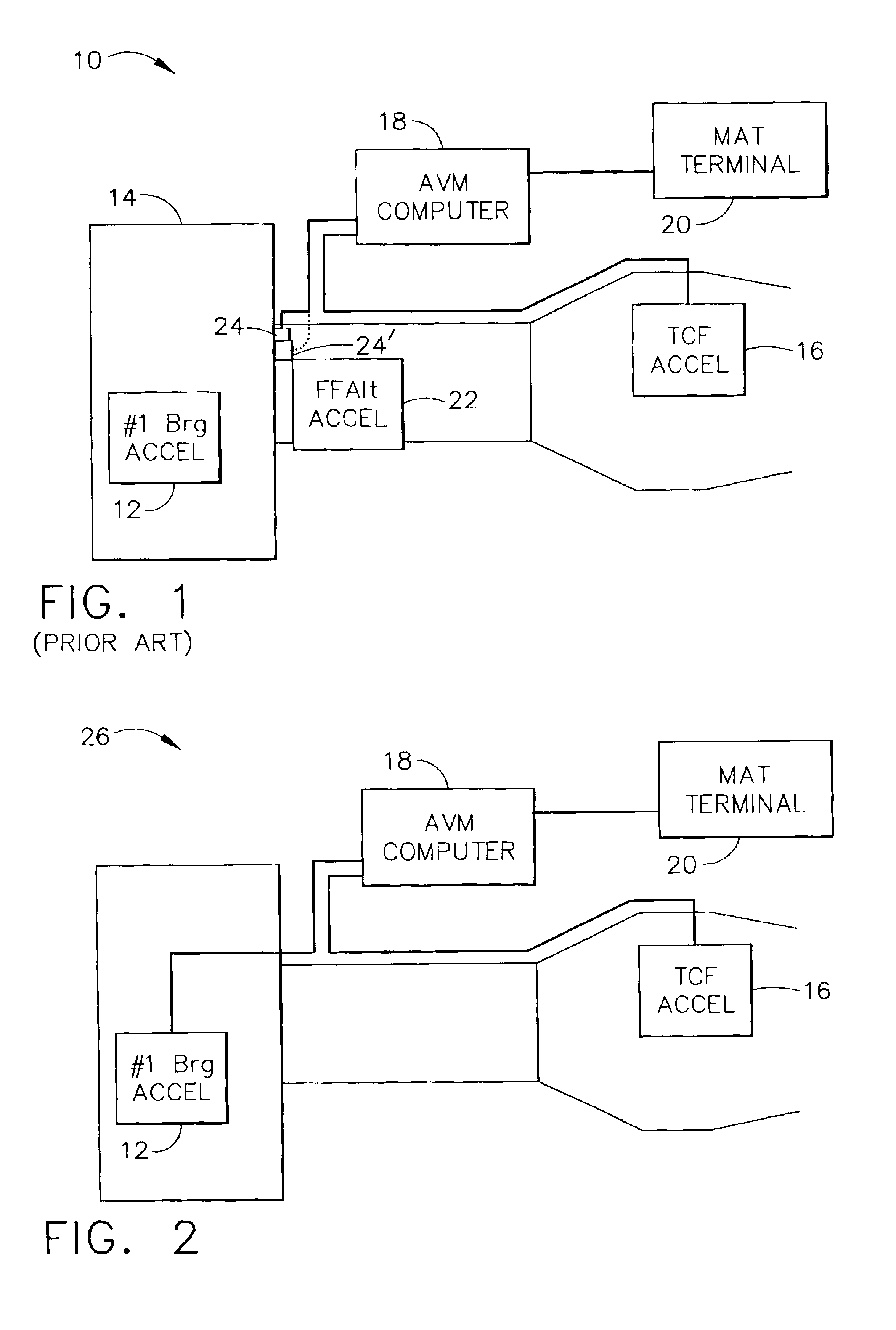
[0010]Referring to FIG. 1, there is illustrated a block diagram of a typical accelerometer configuration of a prior art system 10 for an aircraft engine. In FIG. 1, a first production accelerometer 12 is internally located, typically at the most sensitive location to fan imbalance, such as at the forward most bearing, which is nearest the fan rotor. A second production accelerometer, or external accelerometer, 16 is externally located, for instance on the TCF as shown, although it may be externally located elsewhere such as on the CRF or TRF. Both accelerometers 12 and 14 are associated with a vibration monitoring computer 18, typically located in the electronics bay of the aircraft, or mounted on the engine. The accelerometer signals are typically processed by electronic signal conditioning hardware in the vibration monitoring computer 18 that performs functions such as determining the synchronous vibration levels, calculating balance weights needed to balance the engine, scaling v...


PUM


Abstract

The present invention provides a system and method for using the external accelerometer in an aircraft engine configuration as a backup accelerometer, in the event the internally located production accelerometer fails. The sensor location of the external accelerometer has an acceptable sensitivity to fan imbalance, similar to the location of the former alternate accelerometer. The signal from this external accelerometer is duplicated using software in the signal conditioning hardware, creating the second, alternate signal. As an alternative embodiment, the signal may be duplicated by simply teeing or branching the original signal, using hardware rather than software.

Description

BACKGROUND OF THE INVENTION[0001]The present invention relates to vibration monitoring for aircraft engines and, more particularly, to an accelerometer configuration for measurement of system vibration and indication of engine health for the aircraft engine.[0002]Typical commercial engines have two accelerometers and an associated signal conditioning system to monitor engine health and provide an indication of vibration to the flight crew. On most engines, one of the accelerometers is positioned internally to the engine, at a bearing that is often the most sensitive location to fan imbalance. Since this sensor is internally located, if it fails, a third “alternate” external sensor is usually installed on the fan frame or other external location as a temporary replacement until the next engine teardown when the internally located accelerometer can be replaced. Although the alternate external location is generally not as sensitive to fan imbalance as the internally located sensor, it ...

Claims


Application Information

Patent Timeline
IPC IPC(8): G01M1/28G01M1/00G01M99/00G01D3/08G01H17/00G01M15/14
CPCG01M1/28G01D3/08
Inventor MOLLMANN, DANIEL E.VEN DER MERWE, GERT
Owner GENERAL ELECTRIC CO
Why Eureka
Try Eureka