
Automatically identifying replacement times for limited lifetime components

a technology of limited lifetime components and replacement times, applied in the field of computer systems, can solve problems such as system downtime, personnel may face several challenges, and the storage device in the computer system may fail,

Inactive Publication Date: 2005-06-21
ORACLE INT CORP
View PDF16 Cites 53 Cited by
  • Summary
  • Abstract
  • Description
  • Claims
  • Application Information

AI Technical Summary

Benefits of technology

The system effectively reduces downtime by ensuring that limited lifetime components are replaced on time, minimizing delays and improving customer satisfaction by providing real-time monitoring and notification of replacement needs.

Problems solved by technology

For example, a particular device of a computer system provided by a supplier may fail, causing system downtime.
Service personnel may confront several challenges when attempting to quickly resolve customer problems.
For example, a storage device in a computer system may fail and although service staff knows the storage device must be replaced, the service staff may have limited information regarding the specific configuration of the system.
Resolution of the problem may be delayed as the service staff obtains additional replacement information (e.g., type and part number) for the storage device.
Furthermore, exact configuration information for a particular system may be outdated or may be difficult to access.
Thus, resolution of the problem may be further delayed.
Limited lifetime components tend to stop operating correctly over a predetermined period of time (e.g., performance of the component may degrade over time).
Service personnel may forget to replace some of the limited lifetime components.
For example, service staff may overlook replacement of air filters because seemingly insignificant components such as air filters are typically excluded from on-going preventative maintenance plans.
Downtime may actually increase when customer systems include limited lifetime components that are overlooked for replacement.

Method used


Image

  • Automatically identifying replacement times for limited lifetime components
  • Automatically identifying replacement times for limited lifetime components
  • Automatically identifying replacement times for limited lifetime components

Examples


Embodiment Construction

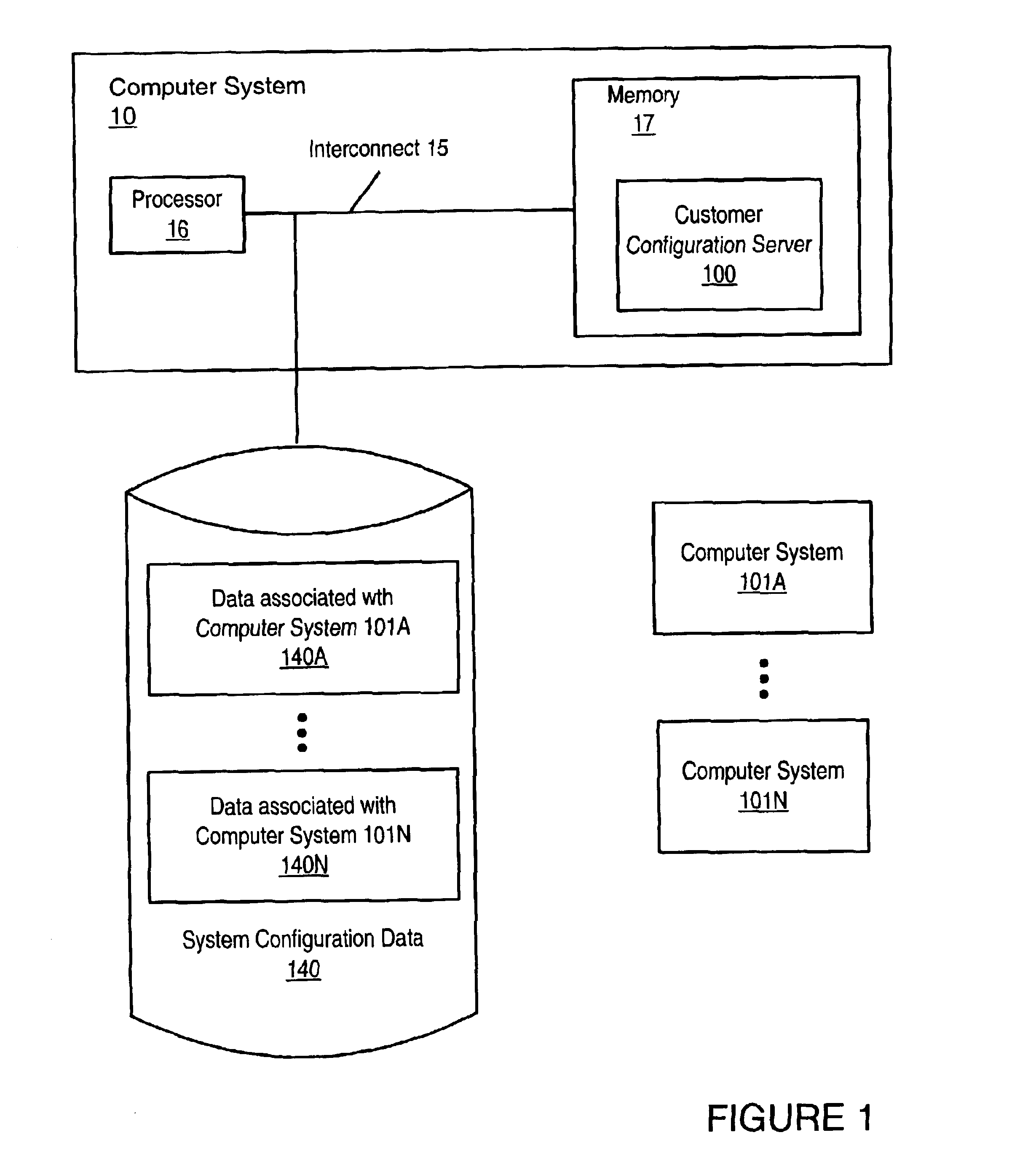
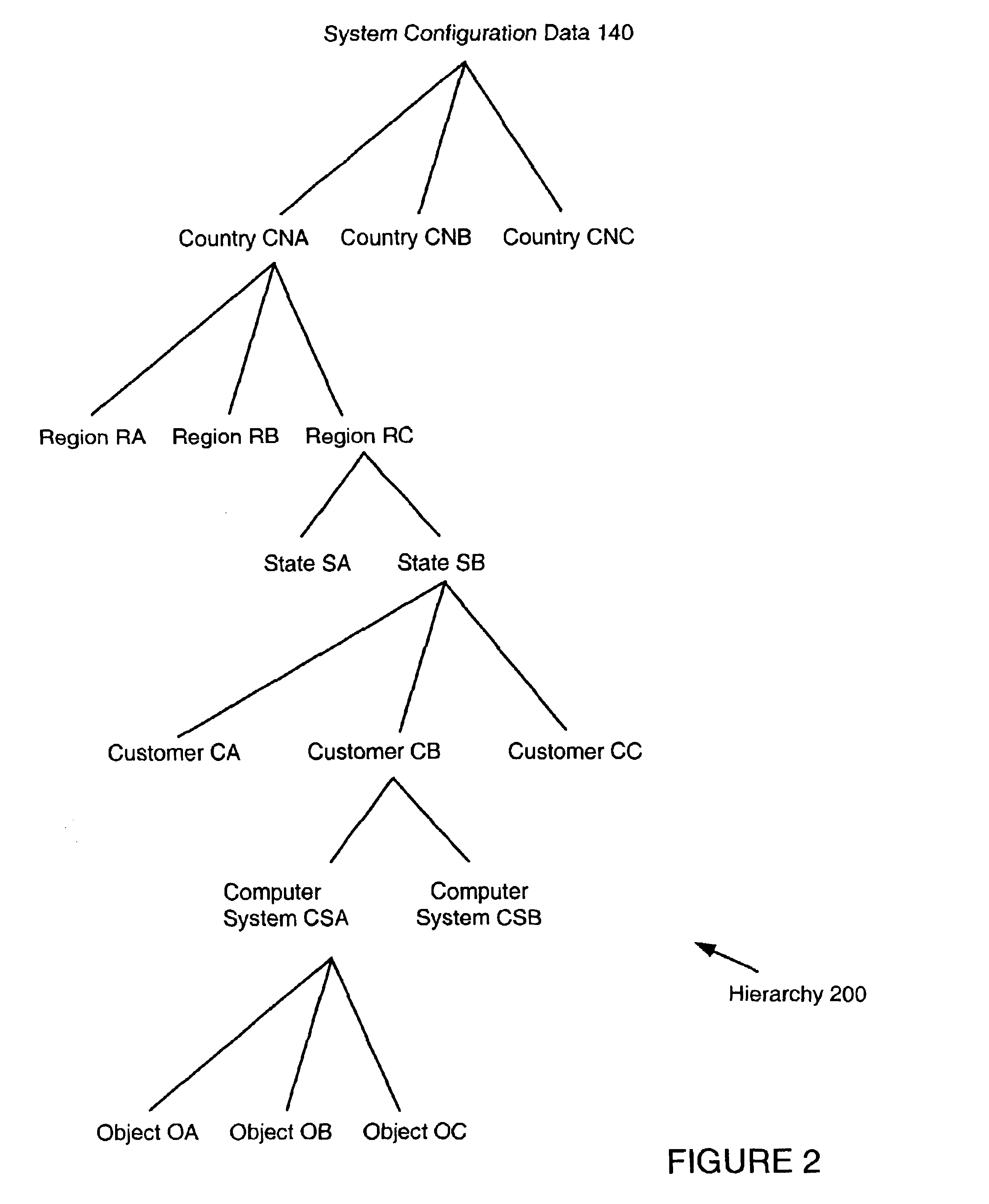
[0024]FIG. 1 shows a computer system 10 that is suitable for implementing various embodiments of a customer configuration server 100 that may provide up-to-date system configuration data 140 for multiple computer systems 101 to service personnel. System configuration data 140 may include data 140A-140N for multiple customers' computer systems 101A-101N, and thus customer configuration server 100 may provide service personnel with a single interface to data 140 representing many of the service personnel's customers' computer systems 101. Customer configuration server 100 may organize system configuration data 140 according to a hierarchy of logical groups within system configuration data 140. Some of those logical groups may group the portions 140N of system configuration data 140 that correspond to a particular computer system 101N together. Customer configuration server 100 may provide access to and / or process system configuration data based on the organizational hierarchy. Note th...


PUM


Abstract

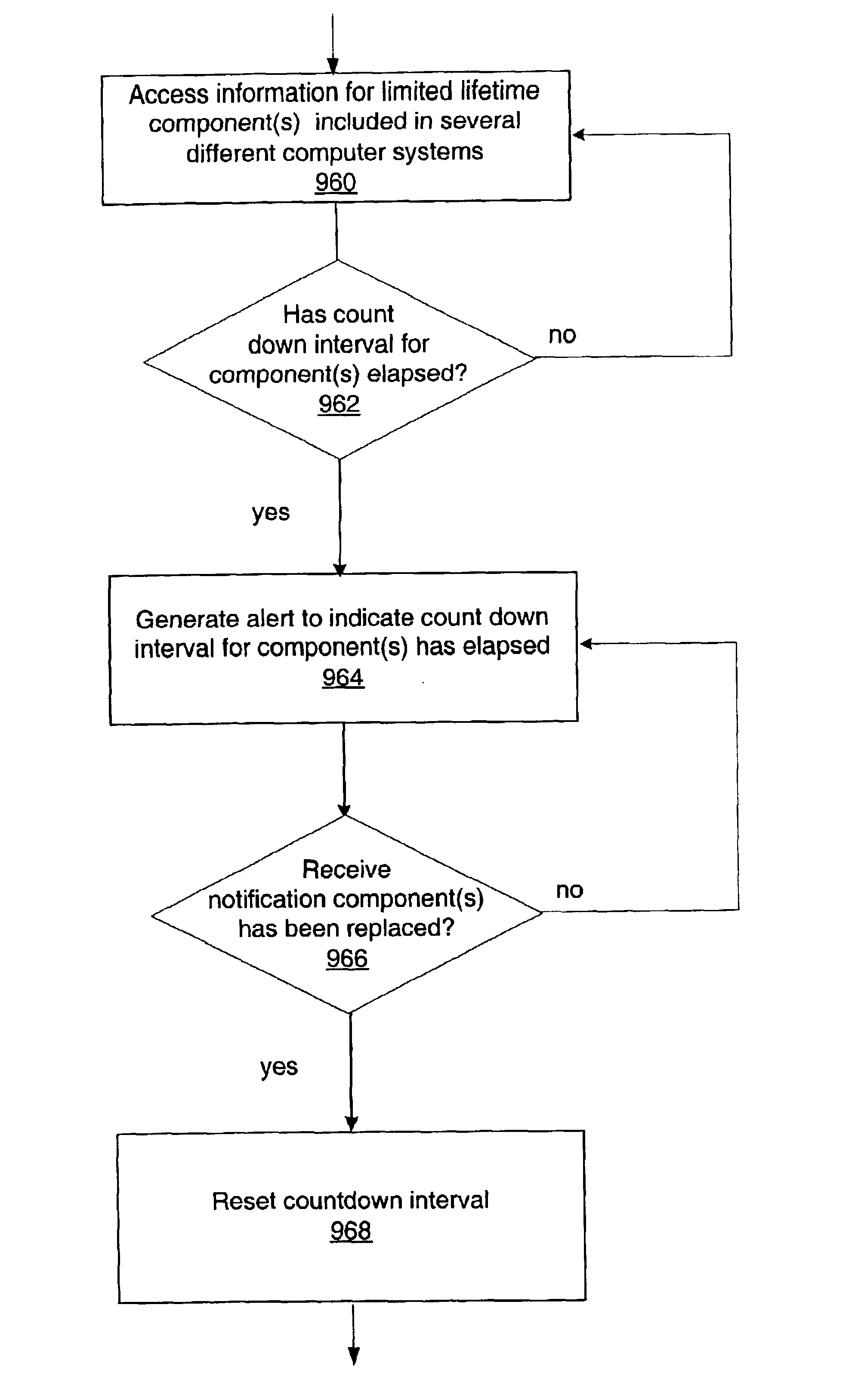
A count down monitor may be configured to automatically generate an alert that one or more limited lifetime components included in multiple computer systems are due for replacement. For example, a system and method that provides up-to-date system configuration data for the multiple computer systems may include and / or interact with one embodiment of a count down monitor. The count down monitor may be configured to automatically generate an alert to indicate one or more of the limited lifetime components are due for replacement. The alert may be visual. The count down monitor may be configured to generate various types of alerts.

Description

BACKGROUND OF THE INVENTION[0001]1. Field of the Invention[0002]This invention relates to computer systems, and more particularly to automatically identifying replacement times of limited lifetime components.[0003]2. Description of the Related Art[0004]With the growing deployment of computer systems and software, users often expect systems to operate without system downtime. Suppliers of computer systems are pressured by customers to provide quick resolution of problems. For example, a particular device of a computer system provided by a supplier may fail, causing system downtime. The customer may pressure the supplier to quickly replace the device in order to minimize downtime. Service personnel, on-site field staff, field engineers, or other resources dedicated to servicing computer systems for customers must quickly identify and solve problems to ensure customer satisfaction.[0005]Service personnel may confront several challenges when attempting to quickly resolve customer proble...

Claims


Application Information

Patent Timeline
Patent Type & Authority Patents(United States)
IPC IPC(8): H04L12/26H04L12/24
CPCH04L41/0253H04L41/06H04L41/0681
Inventor ASHLEY, MARK
Owner ORACLE INT CORP
Learn More