
Members with a thermal break

a member and thermal break technology, applied in the direction of girders, walls, joists, etc., can solve the problems of minimally inhibited heat transfer, fire spreading, and heat transfer

Inactive Publication Date: 2005-06-28
YARROW BAY INDS
View PDF27 Cites 32 Cited by
  • Summary
  • Abstract
  • Description
  • Claims
  • Application Information

AI Technical Summary

Benefits of technology

"The present invention provides a cost-effective solution for heat transfer problems by using a composite of two or more components with a gap between them. This gap is spanned with a thermally insulating, high-strength reinforced polymer, which inhibits the transfer of heat and other vibrations. The resulting structural member is strong, cost-effective, and can be designed easily. It is also non-flammable, resistant to seismic disturbances, high winds, and other environmental factors. Structural members made from the invention do not require servicing to correct structural defects and are immune to attacks by ants and other insects and vermin. The invention can be used in building components and other products such as turbine engine inlet filters. The technical effects of the invention include improved heat transfer resistance, reduced energy consumption, and improved durability and reliability of structures."

Problems solved by technology

One particularly significant disadvantage of such structural members is that they transfer heat from the interior of the building in which they are found to its exterior and in the opposite direction.
This minimally inhibited transfer of heat is deleterious because it can result in the spreading of fire.
And, in less severe instances, the transfer of heat through the steel members can result in an expensive loss of heat from the building in which they are found and / or can increase air conditioning costs by allowing the transfer of heat from the ambient surroundings to the interior of a building.

Method used


Image

  • Members with a thermal break
  • Members with a thermal break
  • Members with a thermal break

Examples


Embodiment Construction

[0036]The discussion which follows deals with multiple embodiments of the invention. To the extent that components of these embodiments are alike, they will be identified by the same reference characters.

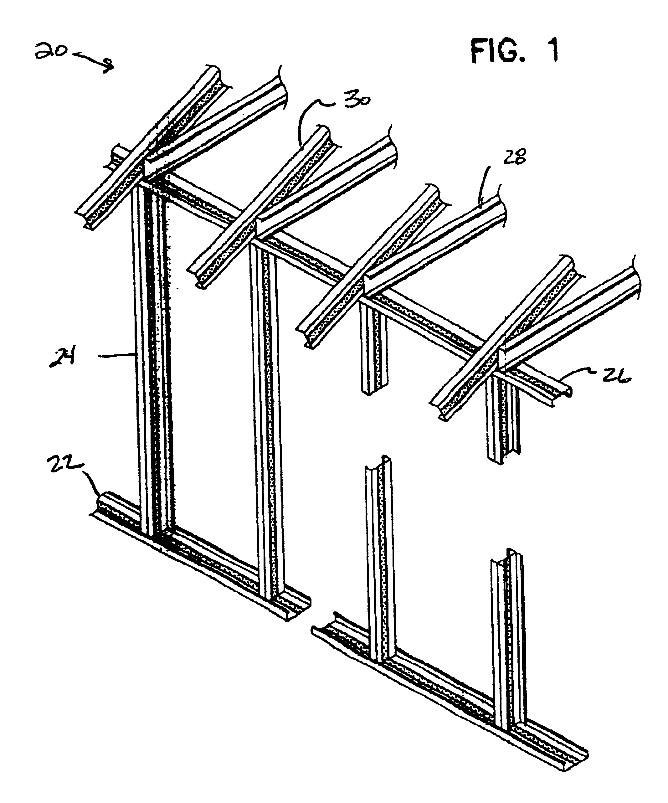
[0037]Referring now to the drawings, FIG. 1 depicts a steel building framework 20. This framework is made up of a sill 22, vertical studs 24, and a top plate 26, or cap, supporting ceiling joists 28 and rafters 30. Framework components 22, 24, 26, and 30 embody, and are constructed in accord with, the principles of the present invention; and rafters 28 may be so constructed as to embody those principles.

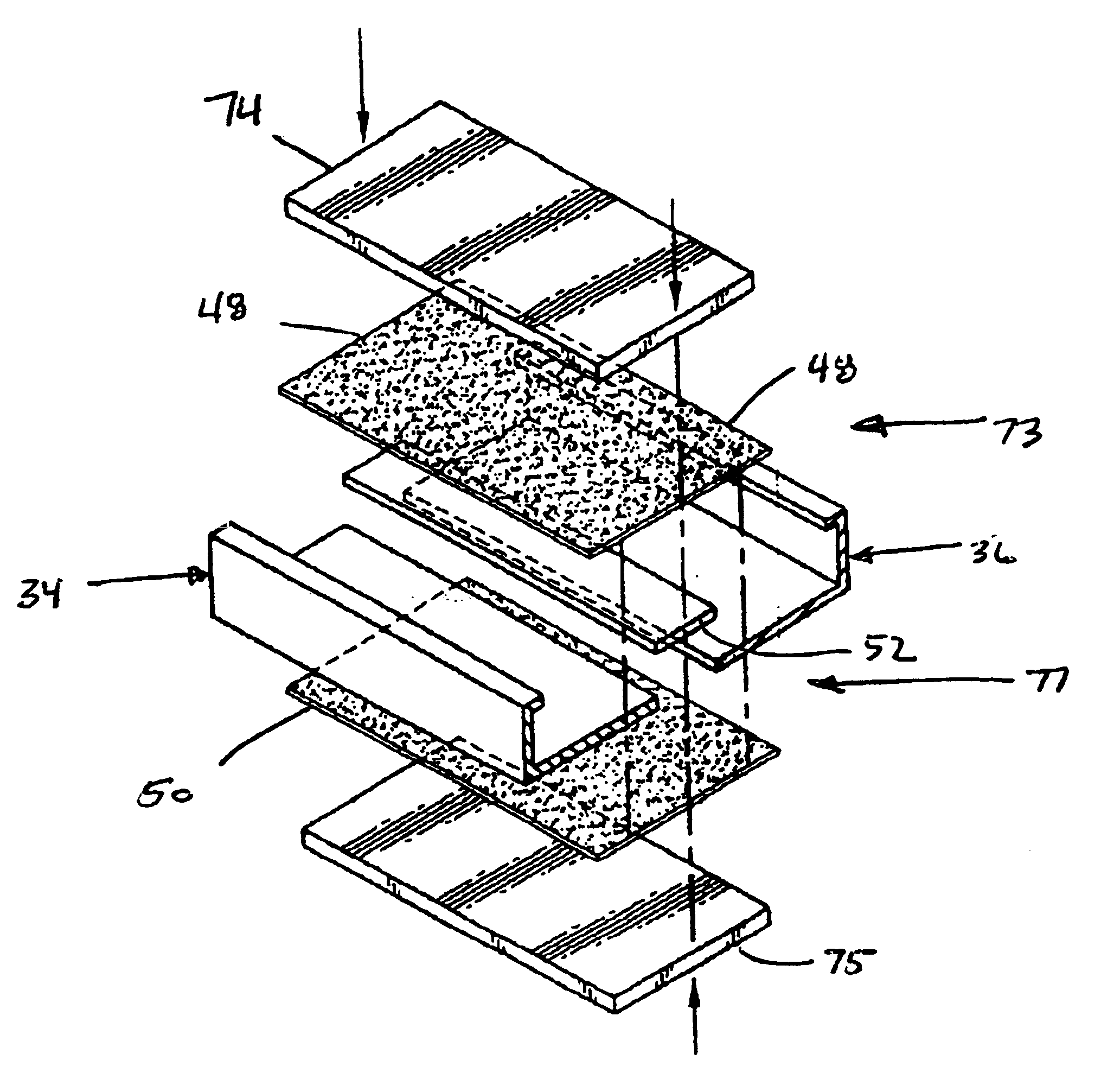
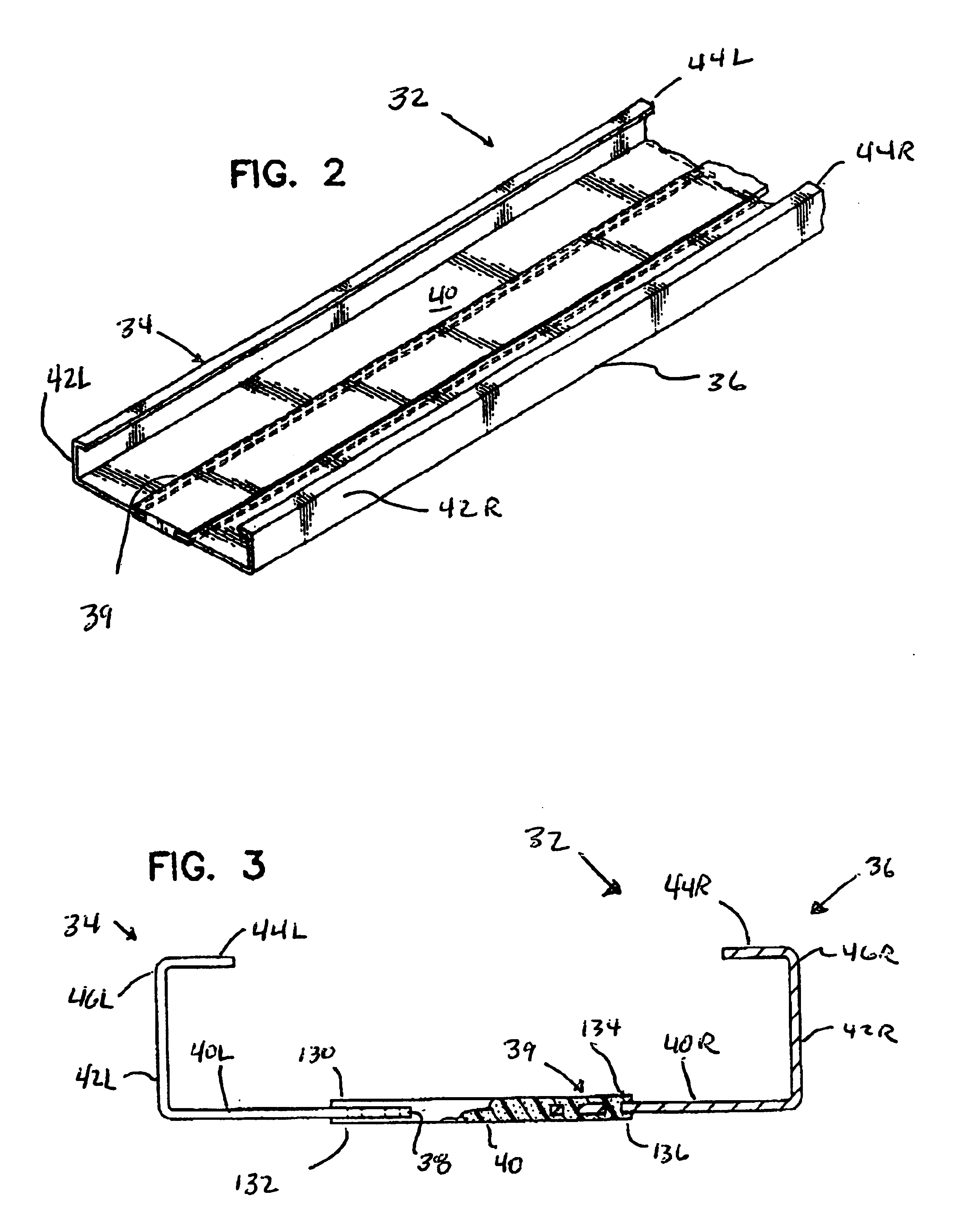
[0038]A representative one of the structural components depicted in FIG. 1 is illustrated in FIGS. 2 and 3 and identified by reference character 32. Structural member 32 has two, substantially identical, mirror image-related, thermally conductive, vibration transmitting (typically steel) components 34 and 36 with a gap 38 therebetween. A third, insulating component 39 spans this gap,...


PUM


Abstract

Members formed from thermally conductive components which have a gap therebetween. The gap is bridged and the conductive components integrated into a composite member by a reinforced polymer. This provides a thermal break which inhibits the flow of heat between the conductive components of the member. This construction also blocks the transfer of sound and other vibrations between the conductive components of the member. The construction also mitigates the formation of condensation on an artifact fixed to one of the components.

Description

TECHNICAL FIELD OF THE INVENTION[0001]The present invention relates to novel, improved members with features which inhibit the transfer of heat from one edge of the member to another. These features also inhibit the transmission of sound and other vibrations and mitigate the formation of condensate.[0002]One important application of the principles of the present invention is found in the provision of heat and vibration transfer resistant structural members for steel framed buildings, and what follows will be devoted primarily to that application of the invention. It is to be understood that this is being done for the sake of clarity and convenience and is not intended to limit the scope of the appended claims.BACKGROUND OF THE INVENTION[0003]Buildings and other structures with exterior walls, ceilings, floors, and / or roofs framed from steel components are ubiquitous because of the superior physical properties of steel vis-a-vis wood, concrete, and other building materials and becaus...

Claims


Application Information

Patent Timeline
Patent Type & Authority Patents(United States)
IPC IPC(8): E04C3/07E04C3/09E04C3/29E04C3/04
CPCE04C3/07E04C3/29E04C3/09E04C2003/0473E04B2/7412
Inventor LINDBERG, VERNE LEROYSPARLING, MICHAEL
Owner YARROW BAY INDS
Learn More