Valve assembly for pressurized fluid vessel

a valve assembly and pressurized fluid technology, applied in the direction of valve operating means/release devices, liquid handling, packaging goods types, etc., can solve the problems of false signals, premature valve closing, and disruption of the control of the associated valve, so as to reduce the back pressure valve closure

Inactive Publication Date: 2005-06-28
FOSTER ASSETS CORPORATION
View PDF13 Cites 20 Cited by
  • Summary
  • Abstract
  • Description
  • Claims
  • Application Information

AI Technical Summary

Benefits of technology

[0007]The use of a secondary valve arranged in this way to control the main valve member ensures the rapid and very effective sealing of the main valve with a simple structural arrangement, utilizing pressure to catch the main valve, with the pressurized fluid serving to force the main valve member against the seat.
[0027]It may be deliberately arranged that there is a small clearance between the sleeve portion and conduit whereby even when closed a small amount of fluid leakage is allowed. This provides a degree of pressure relief within the valve reducing back pressure valve closure.

Problems solved by technology

However, this traditional valve design directs the incoming fluid jets in the general direction of the float, causing the float and the associated valve control to be disrupted from its normal movement, giving false signals and possible premature closing of the valve before filling is complete.
The valve plunger is thereby affected by the control link to this fluctuating float as it moves up and down in the volatile fluid level, and can prematurely close.

Method used


Image

  • Valve assembly for pressurized fluid vessel
  • Valve assembly for pressurized fluid vessel
  • Valve assembly for pressurized fluid vessel

Examples


first embodiment

[0074]The operation is essentially the same as that of the first embodiment; in the empty or near-empty condition of FIG. 6 the spring28 urges the valve member 42 up against the internal shoulder of the diverter 38 whereby the main fluid path is open, and urges the control member downwards, keeping the secondary valve closed with the valve 202 in the valve seat 200. As the tank fills to a predetermined level, the float forces the control member upwardly, opening the secondary valve whereby pressurized fluid impinges on the upper surface of valve member forcing it tight against the valve seat (FIG. 7). With this embodiment it will be appreciated that the pressurized fluid acts directly on the top face of the secondary valve thereby increasing the force of sealing, and thereby ensuring an especially tight seal. Any pulse of pressure, which might arise if the valve on a filling apparatus was suddenly opened would have the effect of increasing the seal effectiveness.

fourth embodiment

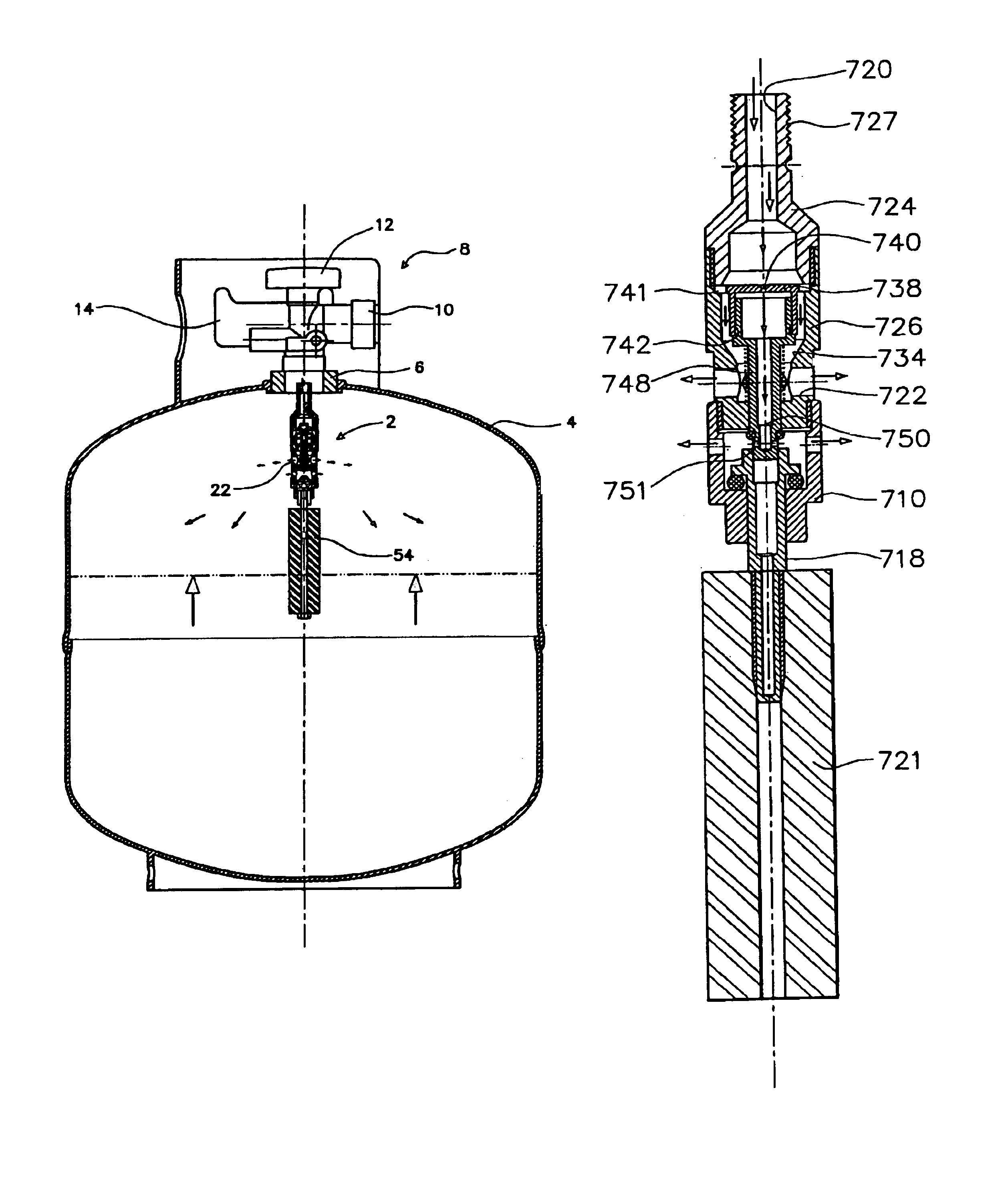
[0075]FIGS. 8 to 10 illustrate the invention. Some of the parts are identical to the previous embodiments and indicated with identical reference numerals. Here, the upper housing part 24 is joined to a lower housing part 326 with the lower housing part defining not just ports 22 but having a further partition 302 extending across the lower housing part and defining an axial opening 304 therethrough. This opening communicates with a lower secondary chamber 306 having its own radially-extending ports 308 of smaller size than the main ports 22. An end cap 310 fitted to the lower housing part serves to support a float and a needle valve assembly as now described. A central upwardly conical guide member 312 is fitted within the end cap 310 facing up into the secondary chamber 306. This has an axial bore therethrough. Below this conical guide member 312 is an cylindrical cavity 314 within which a disc-like support member 316 is arranged. This supports on its underside float shaft 318 whic...


PUM

PropertyMeasurementUnit
pressureaaaaaaaaaa
forceaaaaaaaaaa
vertical displacementaaaaaaaaaa

Abstract

A valve assembly for a pressurized fluid vessel such as a propane tank has a housing defining a main fluid passageway therebetween with a valve seat (734) defined in the main passageway, a main valve member (742) movable against the valve seat (734) to block the passageway, an insert (738) defining an internal chamber within the interior of the housing within which the main valve member (742) is disposed, a secondary fluid flow passageway through the insert (738), through a conduit (748) connected to the main valve body, and through openings (751) in an end of the conduit (748) facing second ports opening into the vessel, and a secondary valve member (760) movable to block the openings (751) under the action of a float (721) on a predetermined fluid level being reached, thereby exposing the main valve member (742) to a pressure differential to close the valve.

Description

BACKGROUND OF INVENTION[0001]The invention relates to valve assemblies for pressurized fluid vessels. More particularly, the invention relates to valve assemblies for controlling the filling of such pressurized fluid vessels.[0002]Various valve assemblies constructed to avoid overfilling of pressurized fluid vessels are known. In U.S. Pat. No. 5,282,496 there is disclosed a two-way valve for filling and draining a gas cylinder. The valve assembly includes a float assembly for control of the opening and closing of the valve as a function of the fluid level in the tank so that the valve can be closed when the fluid level corresponds to the predetermined safe capacity of the vessel. However, this traditional valve design directs the incoming fluid jets in the general direction of the float, causing the float and the associated valve control to be disrupted from its normal movement, giving false signals and possible premature closing of the valve before filling is complete.[0003]U.S. Pa...

Claims


Application Information

Patent Timeline
Patent Type & Authority Patents(United States)
IPC IPC(8): F16K31/18F16K31/34
CPCF16K31/34F17C2250/0413Y10T137/7426Y10T137/7371Y10T137/7478
Inventor CHAN, YET
Owner FOSTER ASSETS CORPORATION
Why Eureka
Try Eureka