Optical transmission element

a transmission element and optical technology, applied in the direction of presses, instruments, fibre mechanical structures, etc., can solve the problems of contamination, handling problems, run out or drip out,

Inactive Publication Date: 2008-03-25
CORNING CABLE SYST LLC +1
View PDF69 Cites 17 Cited by
  • Summary
  • Abstract
  • Description
  • Claims
  • Application Information

AI Technical Summary

Benefits of technology

[0017]A further construction of the fixating element can be a foam film, which is laminated on one or both sides with a swell film. Swell tapes are preferably used for this, where the swell substance containing side is directed towards the foam film. Since the foam filling the empty space between the optical fiber and the transmission eleme

Problems solved by technology

An emerging of the optical fibers poses a problem, especially in the area of connector sleeves, since the fibers being inserted into the connector sleeves bend sharply and can thus break because of emerging.
Such a filling compound has the disadvantage, tha

Method used


Image

  • Optical transmission element
  • Optical transmission element
  • Optical transmission element

Examples


Embodiment Construction

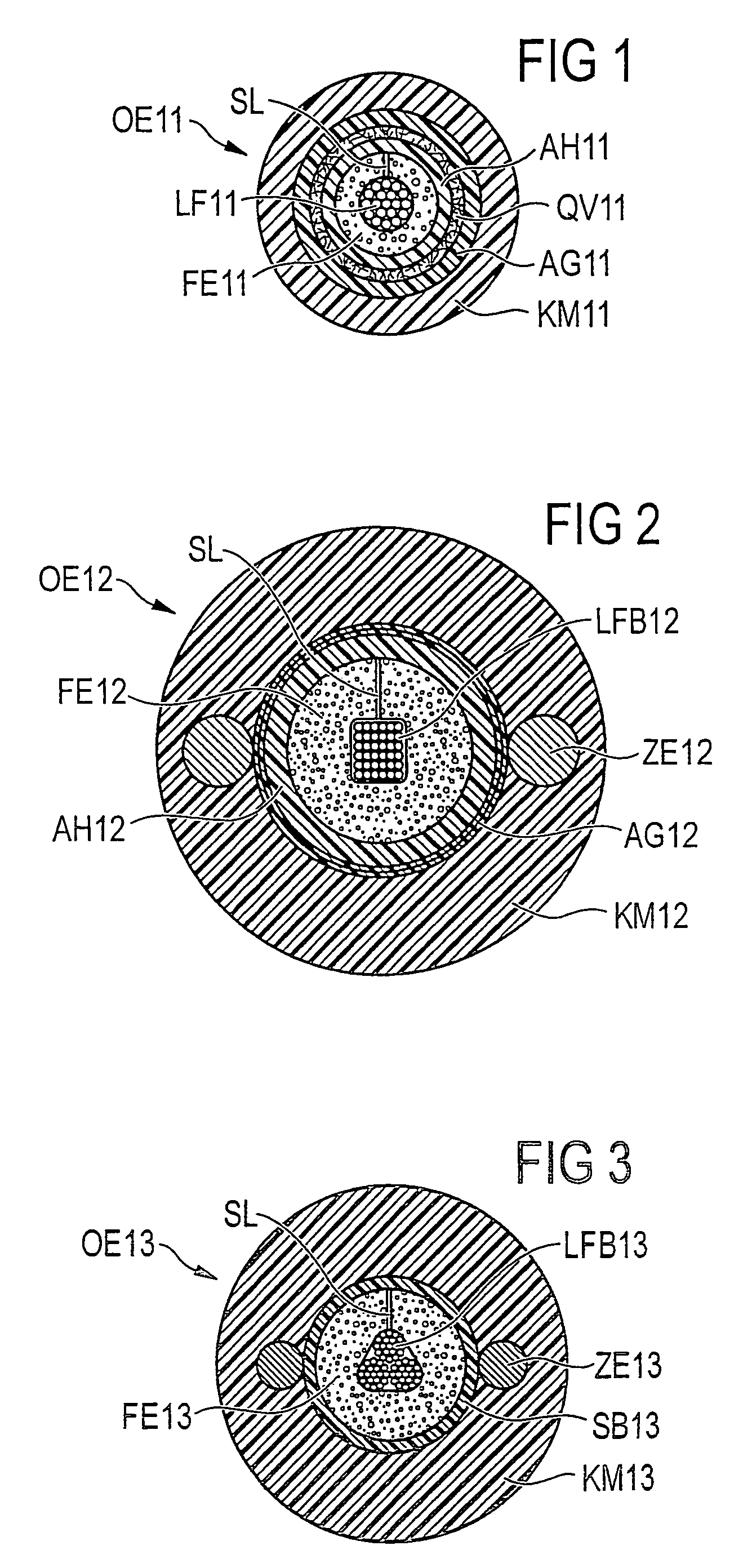
[0026]FIG. 1 shows an optical transmission element OE11 in the form of a cable, which contains several optical fibers LF11 in the form of single fibers. The single fibers LF11 are surrounded by a core covering AH11, where a fixating element FE11 in the form of a compressible foam film is positioned between the fibers LF11 and the core covering AH11. This foam film surrounds the individual fibers almost completely (by the application of the foam film around the fibers a slit SL is formed) and exerts a defined contact pressure against the core covering AH11 and the individual fibers LF11 and thus fixates the fibers in the longitudinal direction of the cable. Due to the flexible construction of the foam film, position changes of the fibers, for example, due to bending or elongation of the cable are made possible. The core covering AH11 is surrounded by a swell tape QV11, which in turn is surrounded by aramid yarns AG11. The cable is enclosed by the cable jacket KM11.

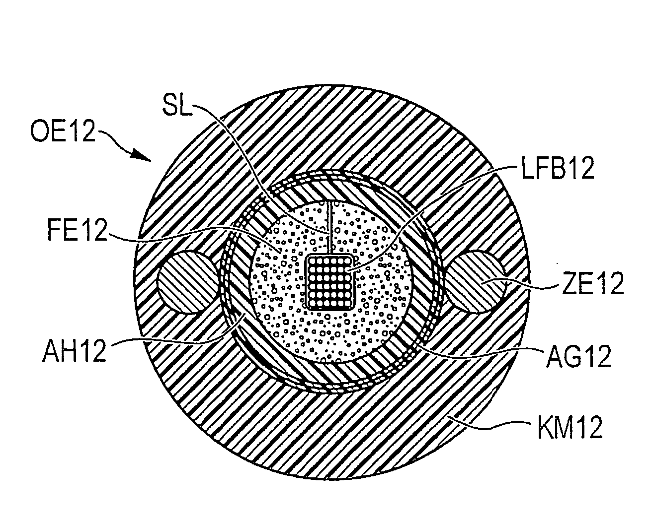
[0027]FIG. 2 shows ...


PUM


Abstract

Between an optical fiber (LF11, LFB12, LFB13) and a surrounding core covering (AH11, AH12, SB13) of an optical transmission element (OE11 to OE13) there is at least one dry and compressible fixating element (FE11 to FE13), which surrounds the optical fiber totally or partially, and which exerts a defined contact pressure against the core covering and against the optical fiber for fixating the optical fiber in the longitudinal direction of the transmission element. The fixating element is further formed and positioned in such a way, that position changes of the optical fiber due to bending or elongation are possible. In this way, unallowable attenuation increases in the optical fiber due to bending or position changes can be avoided.

Description

FIELD OF INVENTION[0001]Between an optical fiber (LB11, LFB12, LFB13) and a surrounding core covering (AH11, AH12, SB13) of an optical transmission element (OE11 to OE13) there is at least one dry and compressible fixating element (FE11 to FE13), which surrounds the optical fiber totally or partially, and which exerts a defined contact pressure against the core covering and against the optical fiber for fixating the optical fiber in the longitudinal direction of the transmission element. The fixating element is further formed and positioned in such a way, that position changes of the optical fiber due to bending or elongation are possible. In this way, unallowable attenuation increases in the optical fiber due to bending or position changes can be avoided.BACKGROUND OF INVENTION[0002]The present invention concerns an optical transmission element with at least one optical fiber and with a core covering surrounding the optical fiber.[0003]Optical transmission elements such as optical ...

Claims


Application Information

Patent Timeline
IPC IPC(8): G02B6/44
CPCG02B6/4405G02B6/4429G02B6/4494G02B6/44384
Inventor SCHNEIDER, REINERHEINZ, EDGARKOSCHWITZ, FRANK
Owner CORNING CABLE SYST LLC
Why Eureka
Try Eureka