Method and system for calibrating ink ejection elements in an image forming device

a technology of ink ejection elements and image forming devices, which is applied in the direction of printing, other printing apparatus, etc., can solve the problems of misalignment of the print carriage assembly, other misalignments, and misalignments, and achieve the effect of reducing the time required

Inactive Publication Date: 2005-06-28
HEWLETT PACKARD DEV CO LP
View PDF6 Cites 3 Cited by
  • Summary
  • Abstract
  • Description
  • Claims
  • Application Information

AI Technical Summary

Benefits of technology

[0012]In comparison to known data center cooling mechanisms and techniques, certain embodiments of the invention are capable of achieving certain aspects, including some or all of the following: (1) scanning a relatively wide test pattern area during a single scanning pass to thereby reduce the time required to perform test pattern s

Problems solved by technology

However, mechanical misalignment of the pens in conventional inkjet printing mechanisms typically results in offsets in the direction of carriage travel and offsets in the direction of print media travel.
This misalignment of the print carriage assembly manifests as a misregistration of the images applied by the pens.
In addition, other misalignments may arise due to the speed of the carriage, the curvature of the platen and/or spray from the nozzles, and the like.
Furthermore, the misalignments may arise from difficulties that may arise during the manufacture of the pens, such as imperfect nozzle shape and/or placement.
Although conventional optical systems have been found to be effective in detecting relative small test strips and certain colors, they also have certain drawbacks and disadvantages.
Therefore, detecti

Method used


Image

  • Method and system for calibrating ink ejection elements in an image forming device
  • Method and system for calibrating ink ejection elements in an image forming device
  • Method and system for calibrating ink ejection elements in an image forming device

Examples


Embodiment Construction

[0018]For simplicity and illustrative purposes, the principles of the present invention are described by referring mainly to an exemplary embodiment thereof. In the following description, numerous specific details are set forth in order to provide a thorough understanding of the present invention. It will be apparent however, to one of ordinary skill in the art, that the present invention may be practiced without limitation to these specific details. In other instances, well known methods and structure have not been described in detail so as not to unnecessarily obscure the present invention.

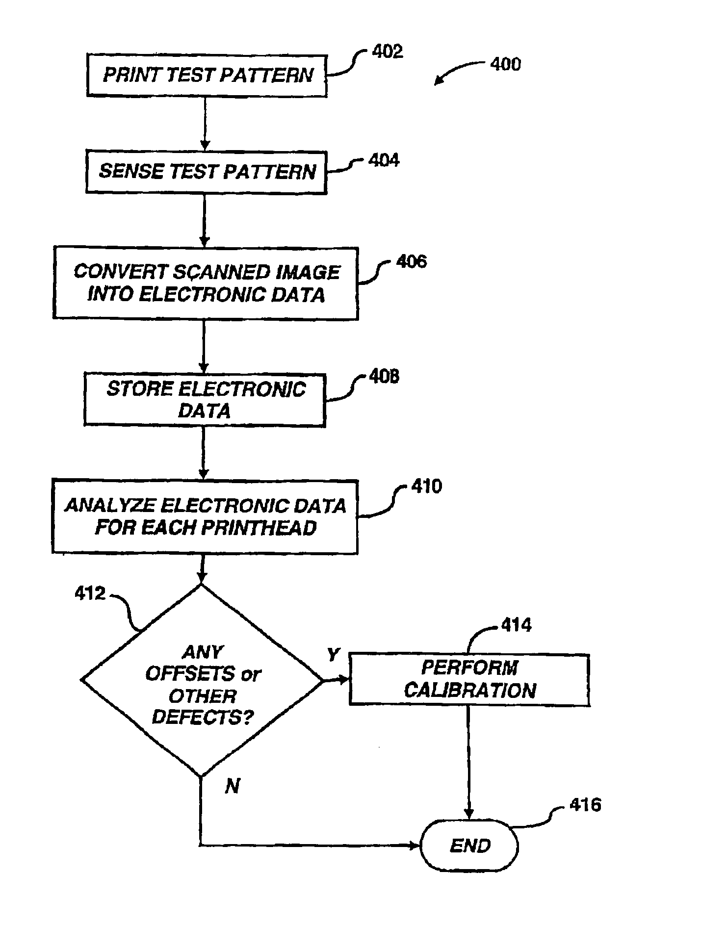
[0019]According to an embodiment of the present invention, the calibration of the printheads of a printing mechanism may be performed in a relatively short period of time as compared to known techniques. In one respect, the time required to perform the calibration may be substantially reduced by implementation of an optical scanner configured to have a relatively wide field of view. The relative...


PUM


Abstract

By implementation of an optical scanner, the calibration of printheads of a printing mechanism may be performed in a relatively short period of time as compared to known techniques. In one respect, the time required to perform the calibration may be substantially reduced by virtue of the relatively wide field of view of the optical scanner. The relatively wide field of view generally enables for the scanning of test patterns to be performed with a relatively fewer number of scanning passes, thus reducing the time required to perform the scanning operations as well as the calibration operations. In addition, the scanning operations may yield relatively more accurate results as compared to known scanning operations. In one respect, optical scanners are capable of detecting smaller drops of ink on print media by virtue of their higher resolution capabilities. In another respect, all of the printed colors may be accurately detected through implementation of a red, green, blue (RGB) charge coupled device (CCD) contained in the optical scanners.

Description

RELATED APPLICATIONS[0001]The present application claims priority to, and is a continuation of, U.S. application Ser. No. 09 / 984,937, now U.S. Pat. No. 6,669,322 filed on Oct. 31, 2001 and entitled “Method And System For Calibrating Ink Ejection Elements In An Image Forming Device”.FIELD OF THE INVENTION[0002]This invention relates generally to printing devices. More particularly, the invention pertains to optics systems and methods for performing ink ejection element detection and calibration operations.BACKGROUND OF THE INVENTION[0003]Inkjet printing mechanisms, e.g., printers, plotters, photocopiers, facsimile machines, etc., typically implement inkjet cartridges, often called “pens” to shoot drops of ink onto a sheet of print media, e.g., paper, fabric, textile, and the like. Some inkjet printing mechanisms carry an ink cartridge with an entire supply of the ink back-and-forth across the sheet. Other inkjet print mechanisms, known as “off-axis” systems, propel only a small ink s...

Claims


Application Information

Patent Timeline
IPC IPC(8): B41J2/165B41J2/01B41J29/46
CPCB41J2/16579
Inventor GASTON, DAVIDSUBIRADA, FRANCESCSOLER, XAVIER
Owner HEWLETT PACKARD DEV CO LP
Why Eureka
Try Eureka