Transparent light emitting members and method of manufacture

a technology of light-emitting members and manufacturing methods, which is applied in the direction of fibre light guides, lighting and heating apparatus, instruments, etc., can solve the problems of more susceptible to breakage during installation of light-emitting members, and achieve the effects of easy moldability, low volume manufacturability, and low cos

Inactive Publication Date: 2005-06-28
LUMITEX
View PDF19 Cites 151 Cited by
  • Summary
  • Abstract
  • Description
  • Claims
  • Application Information

AI Technical Summary

Benefits of technology

[0004]In accordance with another aspect of the invention, the rounded shallow notches or grooves reduce the risk of breakage of the light emitting members during installation or when the members are placed under tension.
[0006]In accordance with another aspect of the invention, the light emitting members with rounded shallow notches or grooves are relatively inexpensive and easy to mold.
[0007]In accordance with another aspect of the invention, the light emitting members with rounded shallow notches or grooves allow for easy low volume manufacturability of the members with any desired amount of smoothness or roughness on the faces of the notches or grooves.

Problems solved by technology

However, such notches are typically relatively sharp grooves, which do not scatter light very finely.
Also the sharp grooves make the light emitting members more susceptible to breakage during installation or when placed under tension.

Method used


Image

  • Transparent light emitting members and method of manufacture
  • Transparent light emitting members and method of manufacture
  • Transparent light emitting members and method of manufacture

Examples


Embodiment Construction

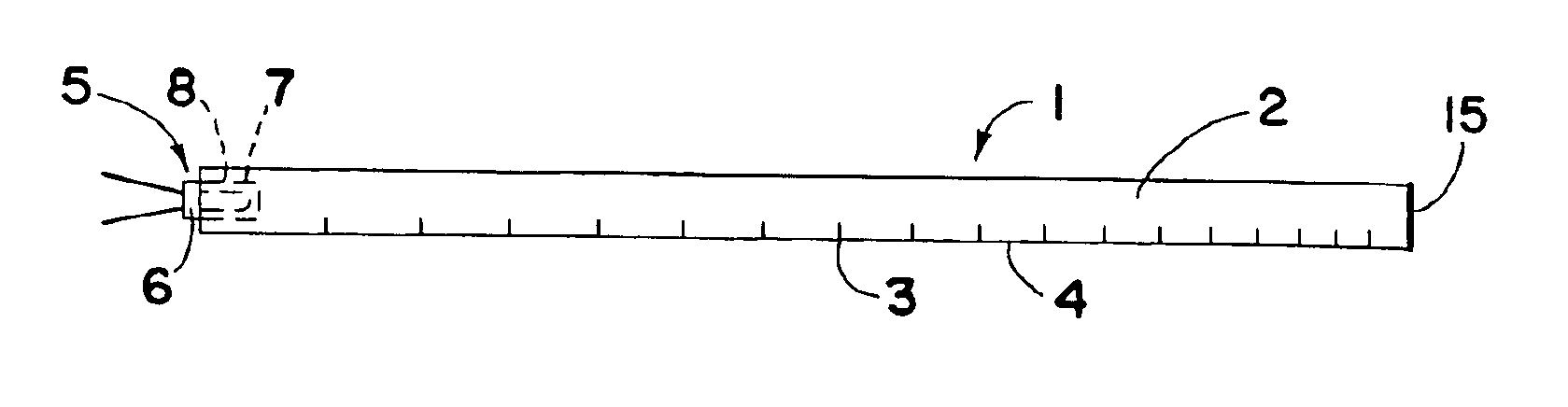
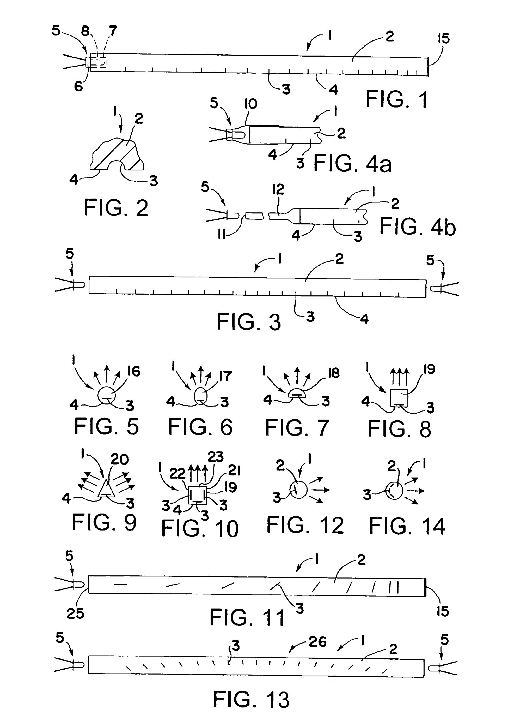
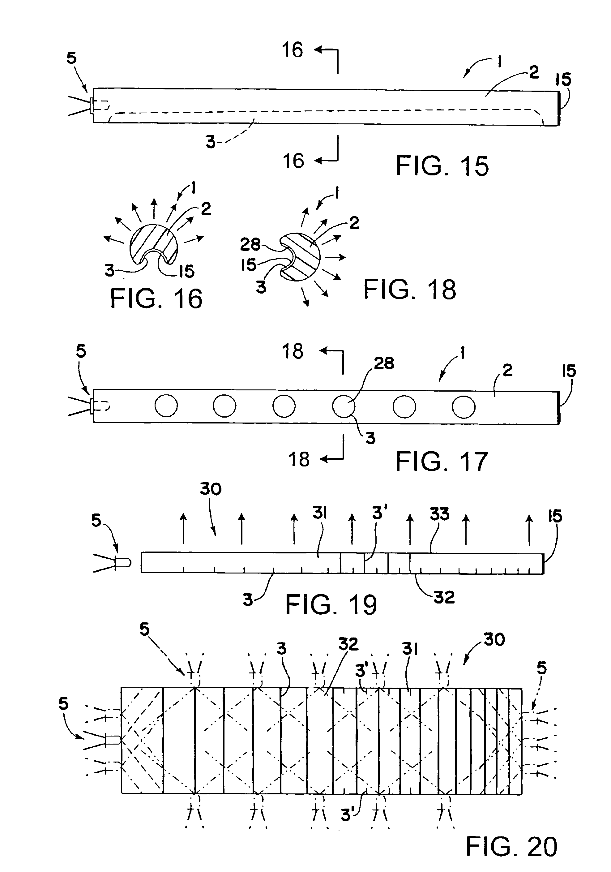
[0039]Referring now in detail to the drawings, and initially to FIG. 1, there is shown one transparent light emitting member 1 of the present invention in the shape of an elongated rod 2 having a pattern of notches or grooves 3 in a surface 4 of the member for causing light that is transmitted through the member by internal reflection to be reflected or refracted out of the member as well known in the art. However, the notches or grooves 3 of the present invention, rather than being relatively sharp grooves as is conventional practice, are rounded shallow notches or grooves each having a generally U or C cross-sectional shape as schematically shown in FIG. 2. These rounded notches or grooves 3 may have a minimum depth and width of radius of no more than a few thousandths of an inch, depending on the length and thickness of the light emitting member, and have the advantage that they will scatter the light more finely than sharp grooves and will reduce the risk of breakage of the memb...


PUM

PropertyMeasurementUnit
transparentaaaaaaaaaa
distanceaaaaaaaaaa
depthaaaaaaaaaa

Abstract

Illuminators include transparent light emitting members having a pattern of rounded shallow notches or grooves in one or more surfaces of the members for causing internally reflected light to be emitted from the members. The notches or grooves may be cut using a circular cutting tool. The relative speed of the cutting tool and feed rate of the cutting tool relative to the members may be controlled to produce a roughened surface on the notches or grooves.

Description

FIELD OF THE INVENTION[0001]This invention relates to transparent light emitting members that have specially shaped notches or grooves in one or more surfaces to create a selected light output distribution from such members and their method of manufacture.BACKGROUND OF THE INVENTION[0002]It is well known that light transparent members including for example rods, panels, films, sheets and plates, can be made into light emitting members or illuminators by notching the members in a certain pattern. However, such notches are typically relatively sharp grooves, which do not scatter light very finely. Also the sharp grooves make the light emitting members more susceptible to breakage during installation or when placed under tension. The light emitting members may be used, for example, as a back light and / or front light for transparent or translucent devices such as LCDs, dials, gauges, pictures, point of sale advertising, decorative devices, and so on. Also such light emitting members may...

Claims


Application Information

Patent Timeline
Patent Type & Authority Patents(United States)
IPC IPC(8): F21V8/00
CPCG02B6/001G02B6/0036G02B6/0021Y10T29/40
Inventor MEZEI, GEORGE A.LOCKWOOD, RICKPAGE, DAVID J.LARSON, DAVID B.
Owner LUMITEX
Why Eureka
Try Eureka