
Optical part for two-way optical communication

a technology of optical communication and optical parts, applied in the field of optical parts for two-way optical communication, can solve the problems of large component count, difficult miniaturization, high cost, etc., and achieve the effect of reducing cost, reducing cost, and reducing complexity

Inactive Publication Date: 2005-06-28
HOSIDEN CORP
View PDF5 Cites 8 Cited by
  • Summary
  • Abstract
  • Description
  • Claims
  • Application Information

AI Technical Summary

Benefits of technology

[0009]It is therefore an object of the present invention to provide an optical part for two-way optical communications which suppresses crosstalk and is highly efficient, small and less expensive.

Problems solved by technology

From the viewpoint of performance, the magnitude of crosstalk becomes issue
Further, since the two lenses 12 and 13 are used with a view to providing increased coupling efficiency, the prior art example is large in the component count and hence is expensive, bulky and difficult of miniaturization.

Method used


Image

  • Optical part for two-way optical communication
  • Optical part for two-way optical communication
  • Optical part for two-way optical communication

Examples


Embodiment Construction

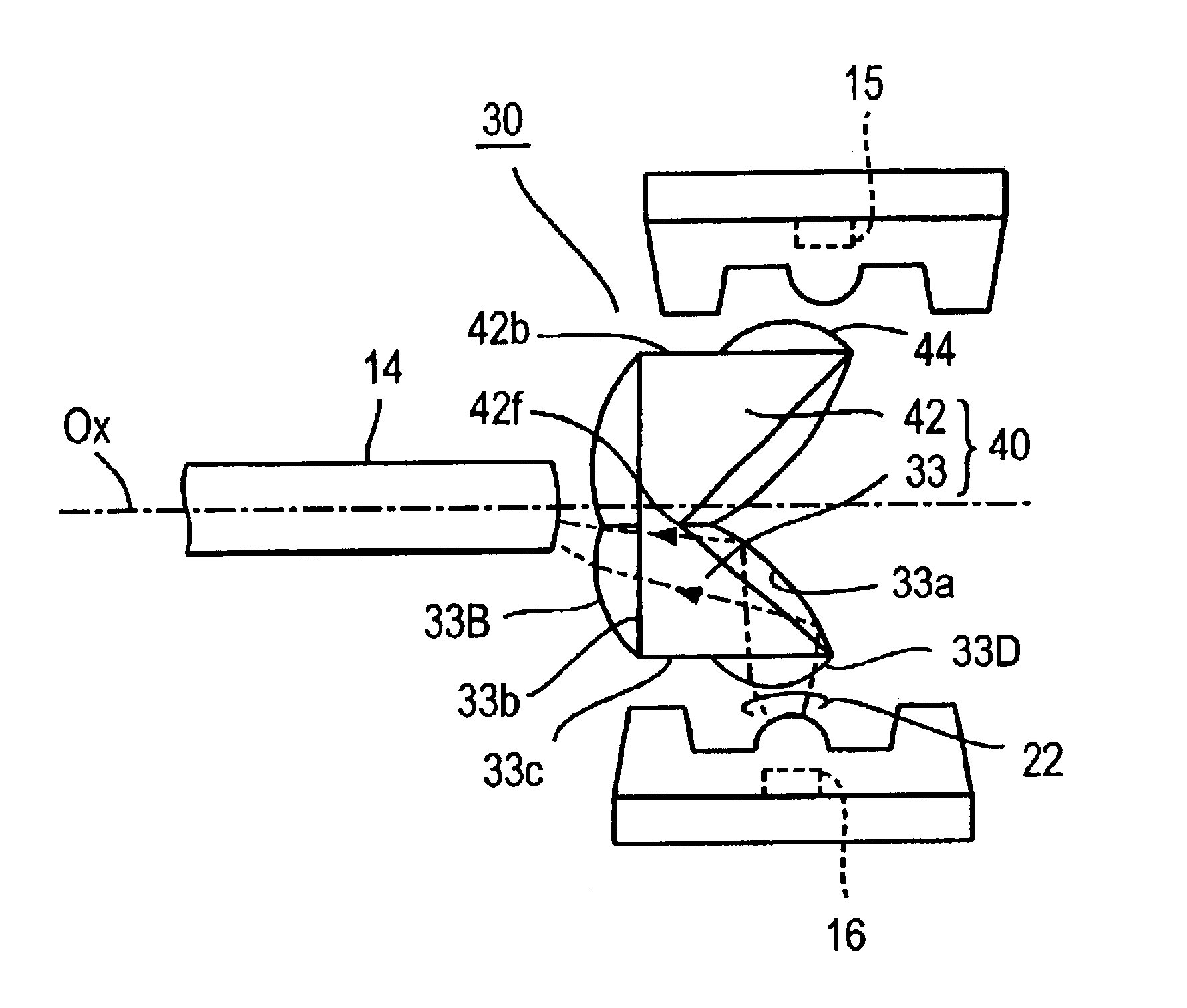
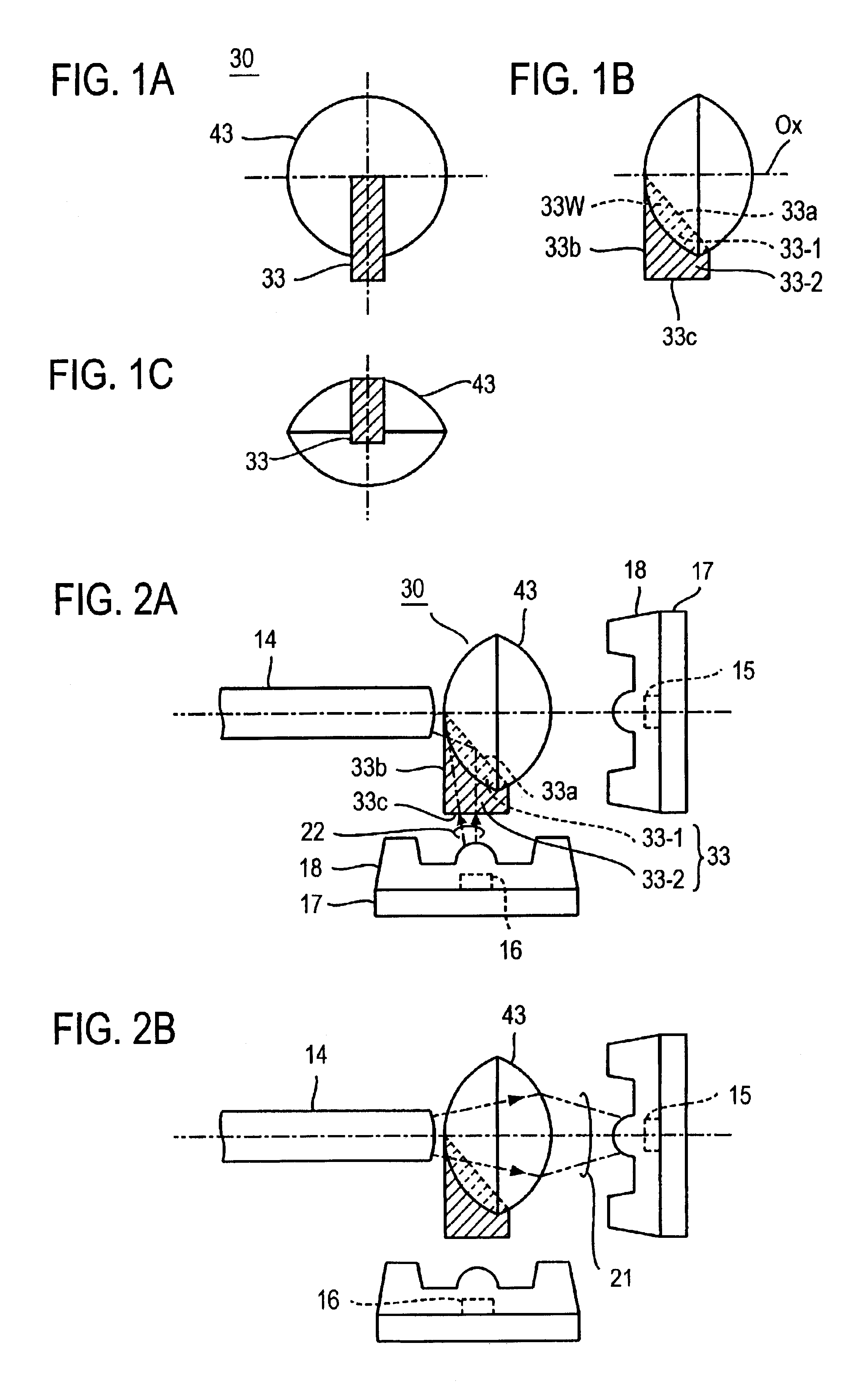
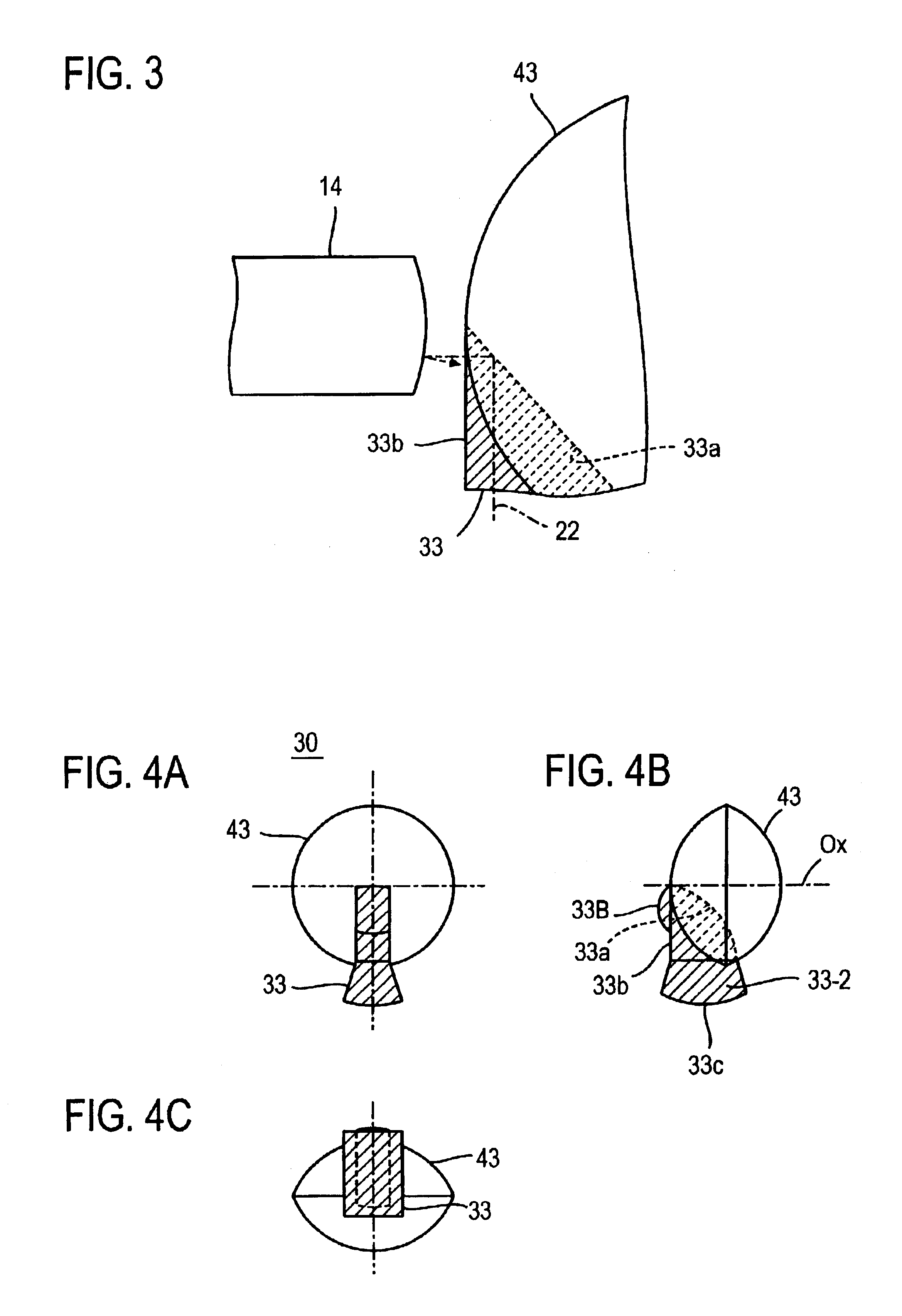
[0049]FIGS. 1A through 1C schematically illustrate an embodiment of the present invention, in which an optical part 30, which is used for two-way optical communications to perform transmission and reception over a single optical fiber, comprises a lens 43 through which received light exiting from the optical fiber end face is focused or converged onto a light receiving element and an optical guide 33 (indicated by hatching) which has a refractive index larger than that of the lens 43 and has its one end portion buried in the lens 43.

[0050]The optical guide 33 is, in this embodiment, substantially a trapezoidal member having, for instance, an about 45°-angled portion 33W. The optical guide 33 is located on the diameter of the aperture of the lens 43 disposed opposite the optical fiber end face. The optical guide 33 is composed of a buried portion 33-1 including the oblique side edge 33a and its marginal portion of the angled portion 33W which are buried in the lens 43 and a portion 3...


PUM


Abstract

An optical guide 43 is partly buried in a lens 43 on the diameter of its aperture, the lens 43 converging received light incident from the end face of an optical fiber onto a light receiving element 15 and the optical conductor 33 having a refractive index larger than that of the lens 43. The optical guide 33 is composed of a buried portion 33-1 and an extending portion 33-2, and transmitting light 22 incident on the optical guide 33 from the end face 33c of the extending portion 33-2 is reflected by a reflecting surface 33a and launched into the optical fiber. The transmitting light 22 is guided by the optical guide 33 to the end face of the optical fiber without leakage to the receiving-side portion.

Description

BACKGROUND OF THE INVENTION[0001]The present invention relates to a optical part for two-way optical communications that transmits and receives lightwave signals over a single optical fiber and, more particularly, to an optical part which is disposed opposite either end face of an optical fiber to guide received light from the optical fiber to a light receiving element and launch transmitting light from a light emitting element into the optical fiber end face.[0002]FIG. 16 schematically shows a prior art example of an optical part of this kind, together with an optical fiber, a light emitting element and a light receiving element. In this example the optical part is made up of a prism 11 and two convergent lenses 12 and 13, through which lightwave signals are transmitted and received.[0003]The prism 11 is right triangular in section, and an optical fiber 14 is disposed with its end face opposite a first one 11a of two surfaces of the prism 11 forming therebetween its right angle, an...

Claims


Application Information

Patent Timeline
Patent Type & Authority Patents(United States)
IPC IPC(8): G02B6/42G02B5/04G02B6/28
CPCG02B6/4246G02B6/4214G02B6/42
Inventor MINE, KEIJINAKAGAWA, HIROSHIISODA, TAKESHI
Owner HOSIDEN CORP
Features
  • Generate Ideas
  • Intellectual Property
  • Life Sciences
  • Materials
  • Tech Scout
  • Unparalleled Data Quality
  • Higher Quality Content
  • 60% Fewer Hallucinations
Learn More