Blade of a wind turbine

a wind turbine and blade technology, applied in the direction of reaction engines, mechanical equipment, machines/engines, etc., can solve the problem that the cost of the tube per metre is many times lower than the cost, and achieve the effect of optimizing the flow properties of the connection par

Inactive Publication Date: 2005-06-28
NEDERLANDSE ORG VOOR TOEGEPAST-NATUURWETENSCHAPPELIJK ONDERZOEK (TNO)
View PDF13 Cites 68 Cited by
  • Summary
  • Abstract
  • Description
  • Claims
  • Application Information

AI Technical Summary

Benefits of technology

[0015]Further optimization of the flow properties of the connection part can be achieved by fitting vortex generators, o

Problems solved by technology

If the connection part is, for example, a tube, the costs of that tube per metre are man

Method used


Image

  • Blade of a wind turbine
  • Blade of a wind turbine
  • Blade of a wind turbine

Examples


Embodiment Construction

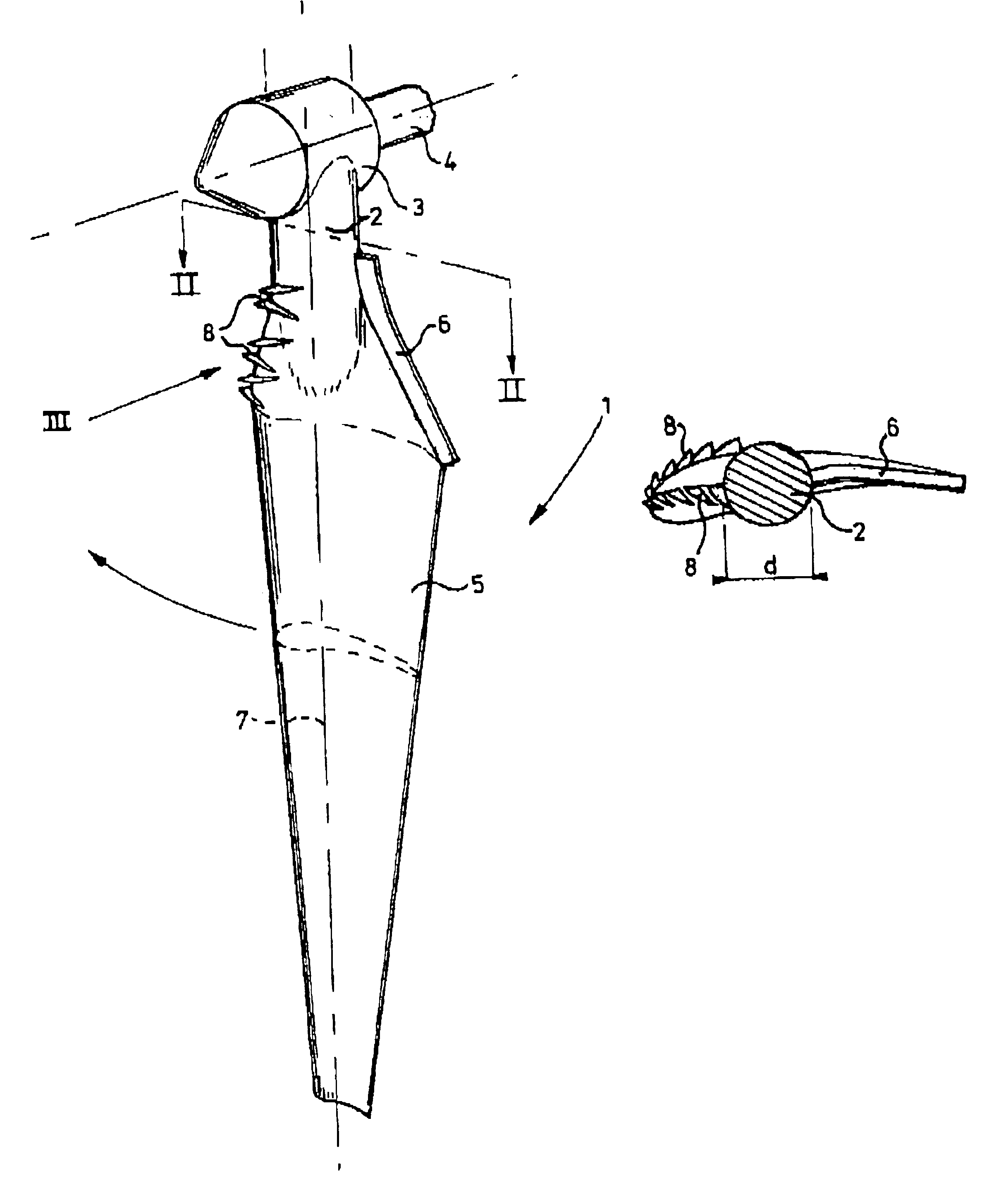
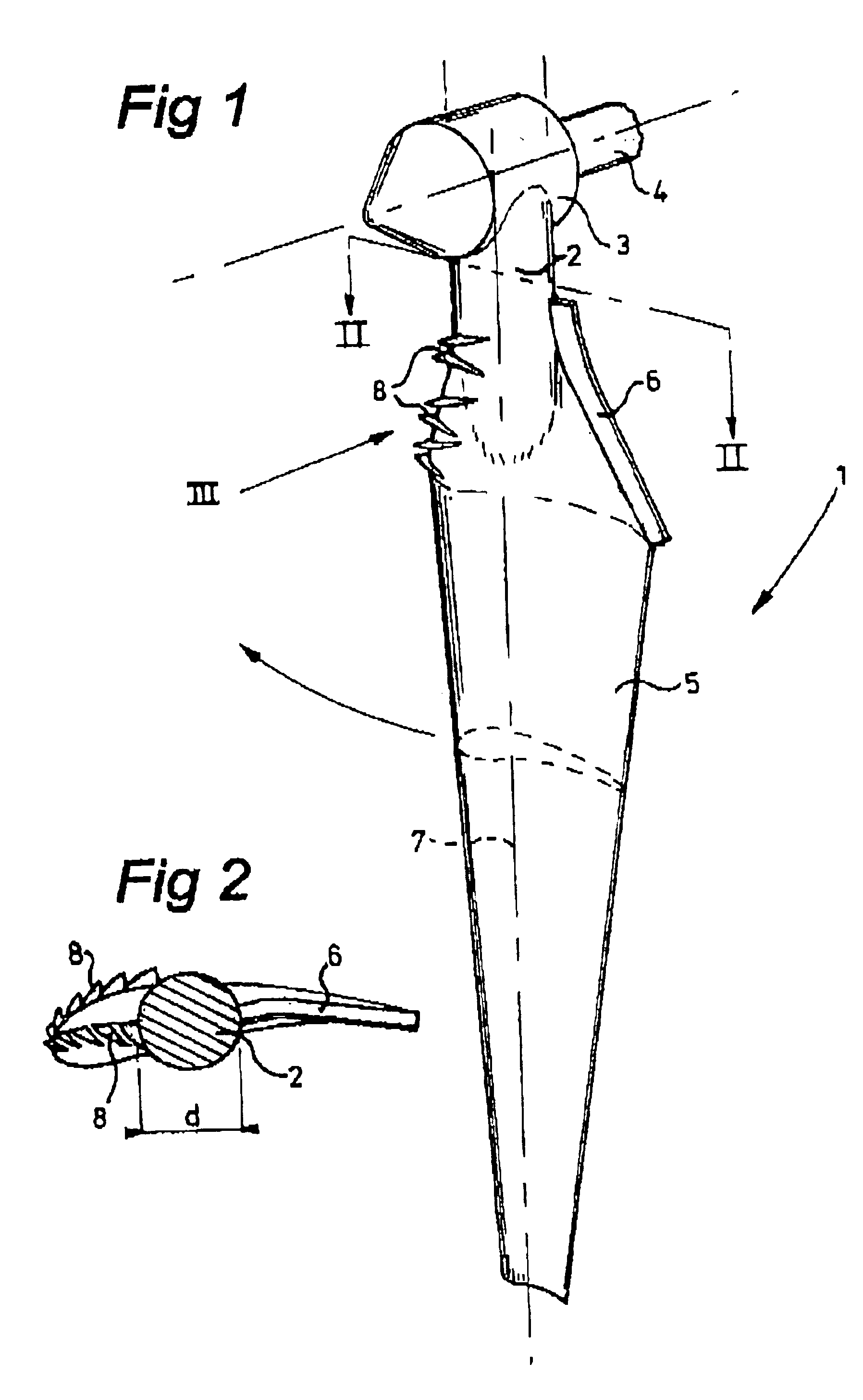
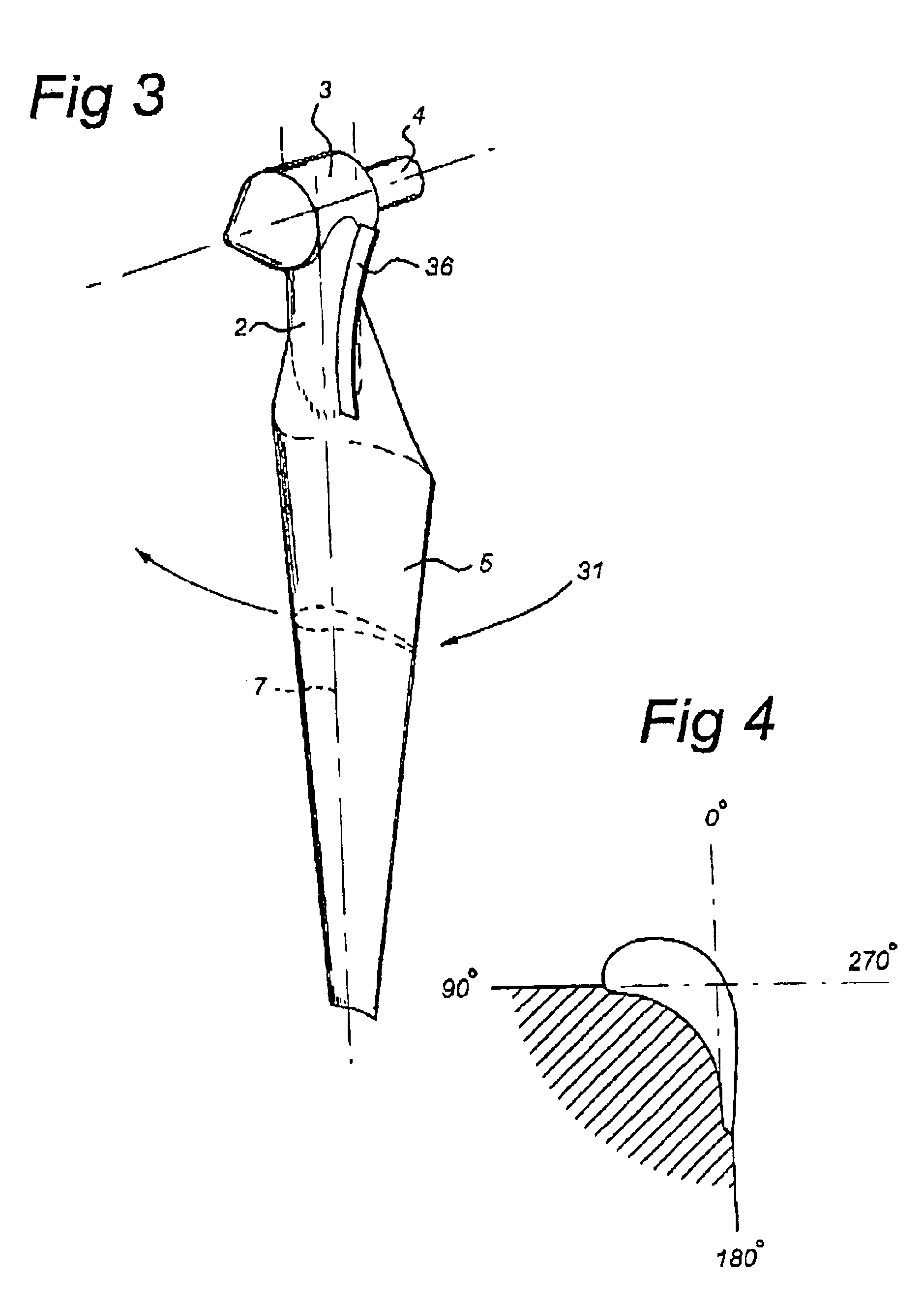
[0023]In FIG. 1 a blade of a wind turbine according to the invention is illustrated by 1. It is composed of a connection part 2. Connection to a hub 3, which forms part of a shaft 4 behind which the actual generator is connected, is possible by means of a flanged connection (not shown). At the other side, connection part 2 is connected to the wind-energy-absorbing profile 5 of the blade 1. In the embodiment shown, the profile is illustrated as a wing profile, and it will be understood that any other shape can be achieved. The axis of the blade is indicated by 7.

[0024]In the example shown here, the connection part 2 is of a circular design and comprises a simple tube. In the general prior art, this tube was of a smooth design, without any further measure being taken.

[0025]According to the invention, it is proposed that a member or rib 6 be fitted on the tube 2. It is also proposed that vortex generators 8 be fitted in the position shown. The vortex generators (not drawn to scale) can...


PUM


Abstract

A blade of a wind turbine is presented. This blade is provided with a root section for connecting the blade to the shaft or hub of the turbine. The blade also contains a wind-energy-absorbing profile which is optimized for wind flow. The output of the wind turbine is increased by providing the root section with a member that is designed in such a way that the assembly consisting of the member and the root section can absorb wind energy and will increase the overall efficiency of the wind turbine.

Description

CROSS REFERENCE TO RELATED APPLICATION[0001]This is the 35 U.S.C. §371 national stage of international application PCT / NL01 / 00483 filed on 28 Jun. 2001, which designated the United States of America.FIELD OF THE INVENTION[0002]The present invention relates to a blade of a wind turbine, comprising a connection part provided at one end with connection means, for connection to the shaft / hub of a wind turbine, and a wind-energy-absorbing profile which is optimized for the wind flow and extends from the other end of the connection part, the connection part being provided with a member that is designed in such a way that the assembly comprising the member and the connection part can absorb wind energy, which member comprises a rib that projects from the connection part.BACKGROUND OF THE INVENTION[0003]Such a blade is known from U.S. Pat. No. 3,874,816A, which discloses a rigid blade root end member fitted on the downstream side of the blade. This end member serves mainly to reinforce the ...

Claims


Application Information

Patent Timeline
IPC IPC(8): F03D1/00F03D1/06
CPCF03D1/0641F05B2240/221F05B2240/30Y02E10/721F05B2240/32F05B2260/96F05B2240/311Y02E10/72F05B2240/3062
Inventor CORTEN, GUSTAVE PAUL
Owner NEDERLANDSE ORG VOOR TOEGEPAST-NATUURWETENSCHAPPELIJK ONDERZOEK (TNO)
Why Eureka
Try Eureka