Real-size simulated pneumatic drag strip ride

a real-size, pneumatic technology, applied in the field of simulation, real-time, pneumatically powered, real-effect drag strip race, can solve the problem of high velocity

Inactive Publication Date: 2005-06-28
RACING ATTRACTIONS
View PDF9 Cites 16 Cited by
  • Summary
  • Abstract
  • Description
  • Claims
  • Application Information

AI Technical Summary

Problems solved by technology

In addition, the noise and exhaust of the dragsters contribute to the real life sensation of the race.
Many amusement rides involve high velocity, dangerous curves and other safety hazards.

Method used


Image

  • Real-size simulated pneumatic drag strip ride
  • Real-size simulated pneumatic drag strip ride
  • Real-size simulated pneumatic drag strip ride

Examples


first embodiment

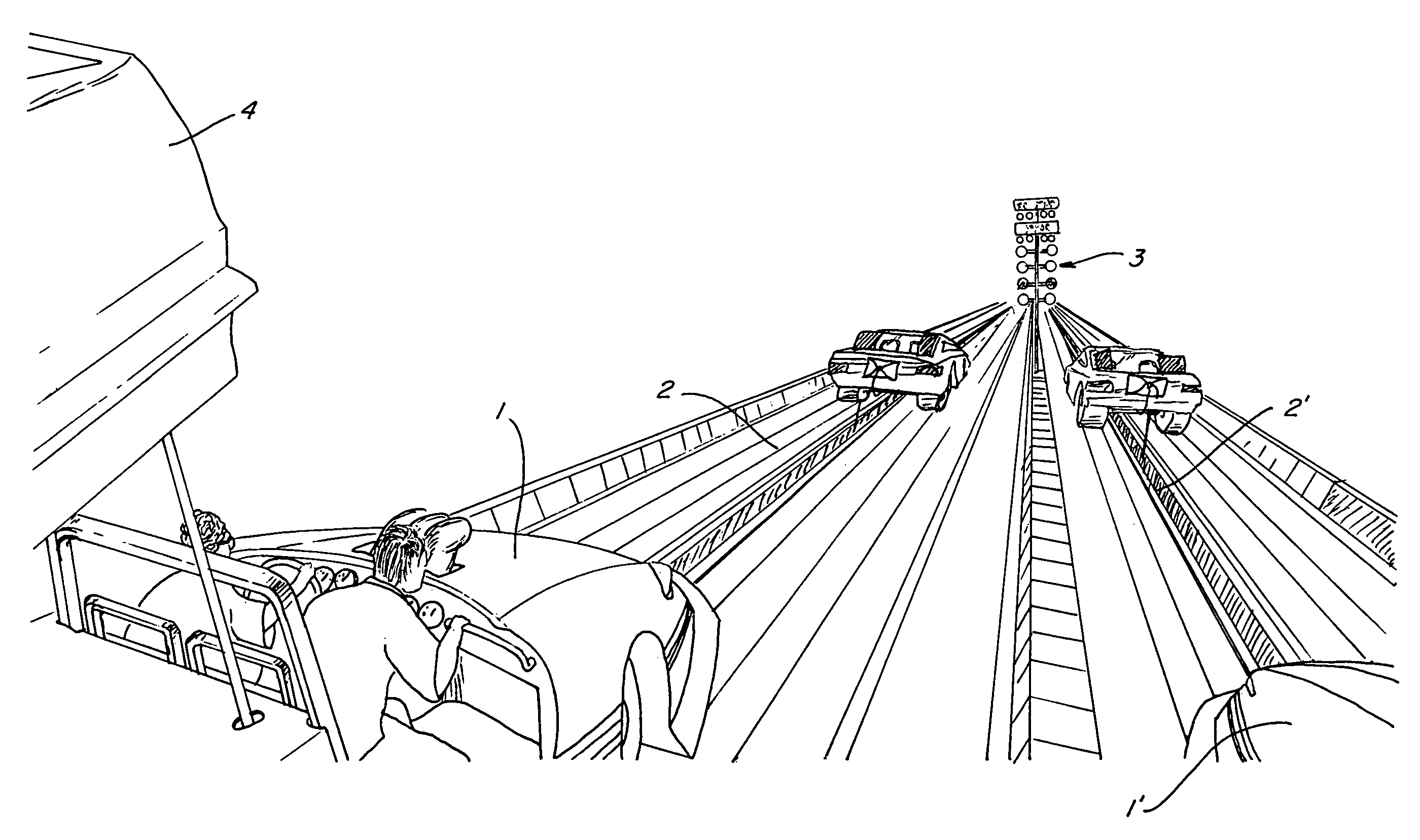
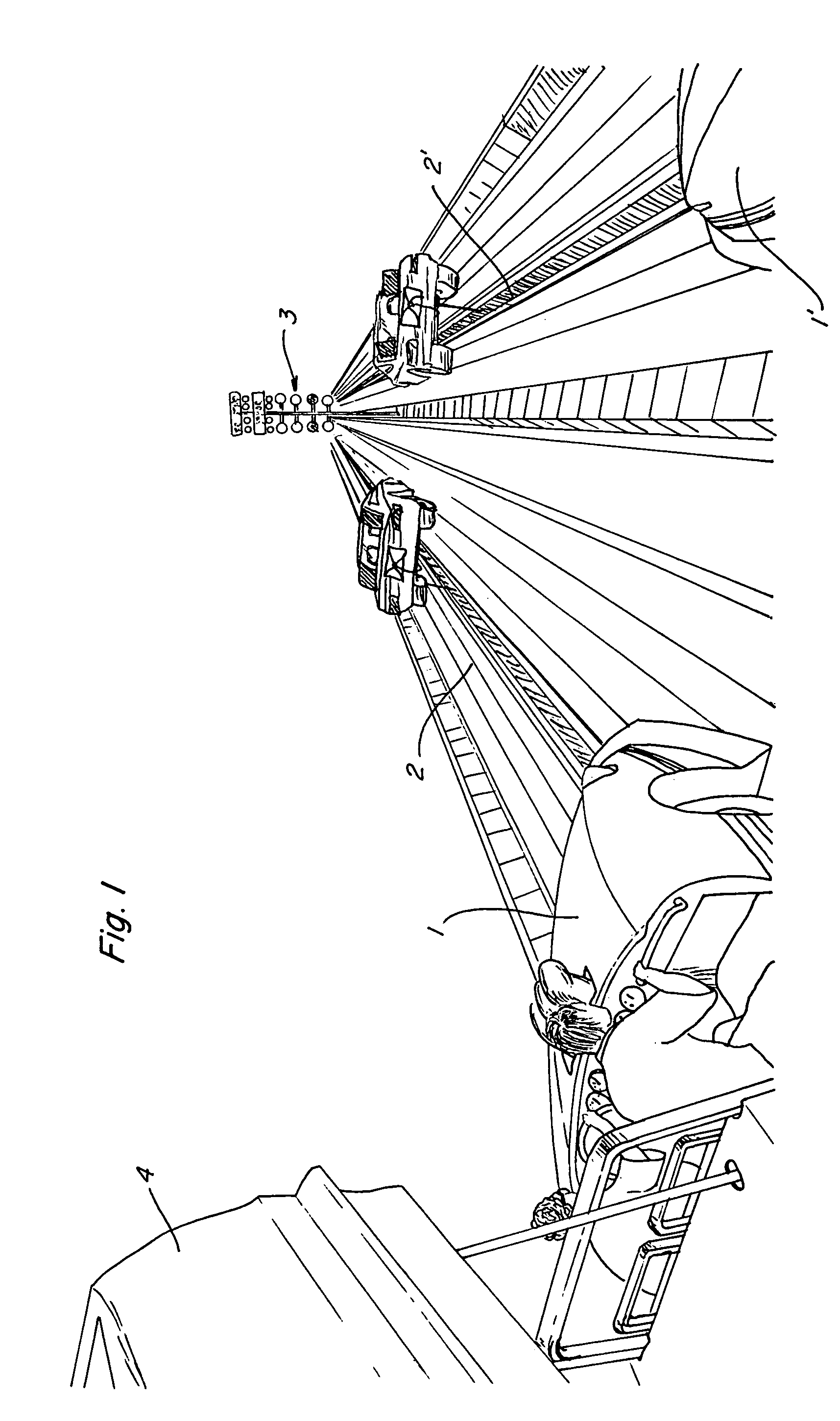
[0028]A real size, simulated dragster race includes an essentially oval raceway with two side-by-side parallel acceleration strips as best shown in FIGS. 1 and 2. Left 1 and right 1′ simulated dragsters are located on left 2 and right 2′ parallel tracks. The race runs for approximately ⅛ of a mile from start to finish in a At the starting line is a signal tower 3. This starting line signal tower has a number of lights such as are usually found in a real life drag race. The lights include a set of green lights to signal “go”, a set of yellow lights to signal “ready” and an electronic readout to signify the winner and the speeds at which each simulated dragster proceeded down the track. Different light systems can be used in practicing this invention.

[0029]Each dragster has an upper, pivotable top 4. This pivotable top 4 moves upwardly (as shown in FIG. 1) to allow passengers to enter the vehicle. The dragster top 4 is then closed (as shown in FIG. 3) for the duration of the ride.

[00...

second embodiment

[0077]The operation of this second embodiment closely simulates the actual drag strip race, including both audio and visual scenarios. As the rider approaches the staging area 59 for participants, the top of the simulated dragster is opened and the driver and / or passenger is seated. The Y-shaped harness is fastened. The driver is within easy reach of the steering wheel and operational buttons 27 and 27′. The driver of the simulated drag strip begins the ride by pushing the button 27 on the dash, which is the start button. This button then actuates the audio engine idling sound and moves the dragster forward slightly, approximately two feet. As the rear simulated wheels 17′ cross the “burn out” roller 83, the rear wheels are rotated by the roller. Simultaneously, the audio simulation of the screeching tires, as well as the simulated smoke emitted from under the track, create the sensory experience of a dragster “burn out”.

[0078]The simulated dragster then approaches the starting line...


PUM


Abstract

A real-size simulated drag strip ride is presented which recreates the physical and visual sensations of a drag race. A pair of real-size dragsters are positioned along specified and controlled parallel linear tracks. The occupant is positioned inside the driver's compartment, with a full safety harness securing him in place in an adjustable seat. The invention includes audio sounds of ignition, “burn-out” and acceleration simulating a drag strip race, as well as simulated smoke from the “burn out” portion of the race preparation. Once the simulated light tower signals that the dragster is set to race, each driver of two, side-by-side vehicles pushes the acceleration pedal to accelerate the vehicle through an initial acceleration zone. The dragsters are propelled by use of a pneumatically powered piston attached to a cable located out of sight underneath the vehicle. The race is finished when the cars pass the finish line. Speeds and the winner are displayed on the starting line tower. The cars are then returned to the loading and unloading area for the next riders.

Description

BACKGROUND OF THE INVENTION[0001]This invention pertains to the field involving amusement rides and drag racing. More particularly this invention describes a simulated, real time, pneumatically powered, real effect drag strip race. This drag strip race may be a stand-alone amusement ride located in population centers or other amusement areas such as parks. This amusement ride is also well adapted to theme parks or amusement parks. These theme parks or amusement parks are located throughout the United States and the world. Such amusement parks are located in England, France, Germany, Russia, and even China. Actual drag strip races are common in the United States and throughout the rest of the world. This particular invention discloses a stimulated drag strip ride for use by the paying public.[0002]Amusement rides are often simulations of much more dangerous real life rides or adventures. Many examples of these real life amusement rides have been created at large and small amusement p...

Claims


Application Information

Patent Timeline
Patent Type & Authority Patents(United States)
IPC IPC(8): A63G7/00A63G25/00A63K1/00
CPCA63G7/00A63K1/00A63G25/00
Inventor NORBURY, STEVEN
Owner RACING ATTRACTIONS
Why Eureka
Try Eureka