Switch

a switch and knob technology, applied in the field of switches, can solve the problems of bringing about a failure, a large number of integrating steps, and troublesome operation of the switch knob, so as to facilitate the integration process, facilitate the occurrence of a failure in step, and simplify the effect of integration

Inactive Publication Date: 2005-06-28
NILES PARTS CO LTD
View PDF8 Cites 21 Cited by
  • Summary
  • Abstract
  • Description
  • Claims
  • Application Information

AI Technical Summary

Benefits of technology

[0022]According to the invention of the second aspect, in addition to the effect of the invention of the first aspect, the elastic portion is the elastic projection projected from the switch knob into the opening of the knob attaching portion, the receive portion is the engaging hole provided at the knob attaching portion for fitting and holding the front end of the elastic projection and therefore, in inserting the operating lever portion of the switch knob from the opening of the knob attaching portion, the elastic projection can be fitted to and held by the engaging hole. Therefore, integrating is facilitated and occurrence of a failure in step can firmly be restrained. Further, the switch knob can automatically be returned to the original neutral portion by the elasticity of the elastic projection.
[0023]According to the invention of a third aspect, in addition to the effect of the invention of the second aspect, the engaging hole is provided at the bottom portion of the spring containing portion capable of containing the coil spring used in the switch knob having other specification, the bottom portion of the spring containing portion is formed in the shape of the taper hole converging toward the engaging hole and therefore, in integration, when the elastic projection is inserted into the spring containing portion and the front end is butted to the bottom portion, the front end of the elastic projection can be fitted to the engaging hole by being guided by the bottom portion in the shape of the taper hole. Further, when the elastic projection is inserted with the spring containing portion larger than the engaging hole as a measure, as-described above, the elastic projection can be inserted into the engaging hole. Therefore, integration can further be facilitated and occurrence of a failure in step can be restrained further firmly. Further, the spring containing portion can contain the coil spring used in the switch knob having another specification and the switch knob having the other specification, for example, a switch knob of an auto switch can be attached by commonly using the switch case.
[0024]According to the invention of a fourth aspect, in addition to the effect of the invention of the first aspect, the elastic portion is the elastic leg portion projected from the switch knob to the outer face of the case, the receive portion is the outer face of the case, the elastic leg portion is brought into elastic contact with the outer face of the case and therefore, by only carrying out an operation of attaching the switch knob to the knob attaching portion, the elastic leg portion can be brought into elastic contact with the outer face of the switch case. Therefore, special consideration for bringing the elastic leg portion to the outer face of the switch case is dispensed with, integration is further simplified and occurrence of a failure in step can further firmly be restrained. Further, by making the elastic leg portion elastically spring to the outer face of the switch case in the state of integrating the switch knob, the elastic spring force can be operated to a portion of the switch knob axially supported by the switch case and play of the switch knob relative to the knob attaching portion can further firmly be prevented.
[0025]According to the invention of a fifth aspect, in addition to the effect of the invention of the fourth aspect, the groove for fitting and guiding the front end of the elastic leg portion is provided at the outer face of the switch case and therefore, movement of the elastic leg portion can be stabilized and operation feeling of the switch knob can be promoted. Further, in integrating the switch knob, the hand of the operator can be prevented from touching the elastic leg portion and destruction of the elastic leg portion can be prevented.
[0026]According to the invention of a sixth aspect, in addition to the effect of the invention of the first aspect, the elastic portion is formed by providing the through hole at the edge portion of the switch knob, at either one of the elastic portion and the receive portion, the projection in contact with the other side is provided and the elastic portion can be deformed by changing the situation of bringing the side of the elastic portion or the side of the receive portion into contact with the projection by operating to pivot the switch knob.
[0027]Therefore, the elastic portion can be brought into a both end holding state and rigidity of the elastic portion per se can be increased. Therefore, the wall thickness of the elastic portion or the like can be reduced and light-weighted formation and small-sized formation can further be expedited. Further, since the rigidity of the elastic portion is increased, a jig pin at the elastic portion is easy to be drawn from a mold and fabrication can be facilitated.

Problems solved by technology

However, according to the above-described structure, in integrating operation, there is constituted a procedure of containing the coil spring 213 in the spring containing portion 211, thereafter inserting the steel ball 215 thereinto, coating grease and integrating the switch knob 203 and therefore, there poses a problem that a number of integrating steps is large.
Further, according to the structure as shown in FIG. 25, there is a concern of bringing about a failure in step such as a failure in inserting the coil spring 213, detachment of the steel ball 215 or the like and there is a concern of bringing about trouble in operation of the switch knob 203.
Further, a number of parts of the coil spring 213, the steel ball 215 and the like is large and integration and parts control are complicated to thereby cause to increase cost.

Method used


Image

  • Switch
  • Switch
  • Switch

Examples


first embodiment

(First Embodiment)

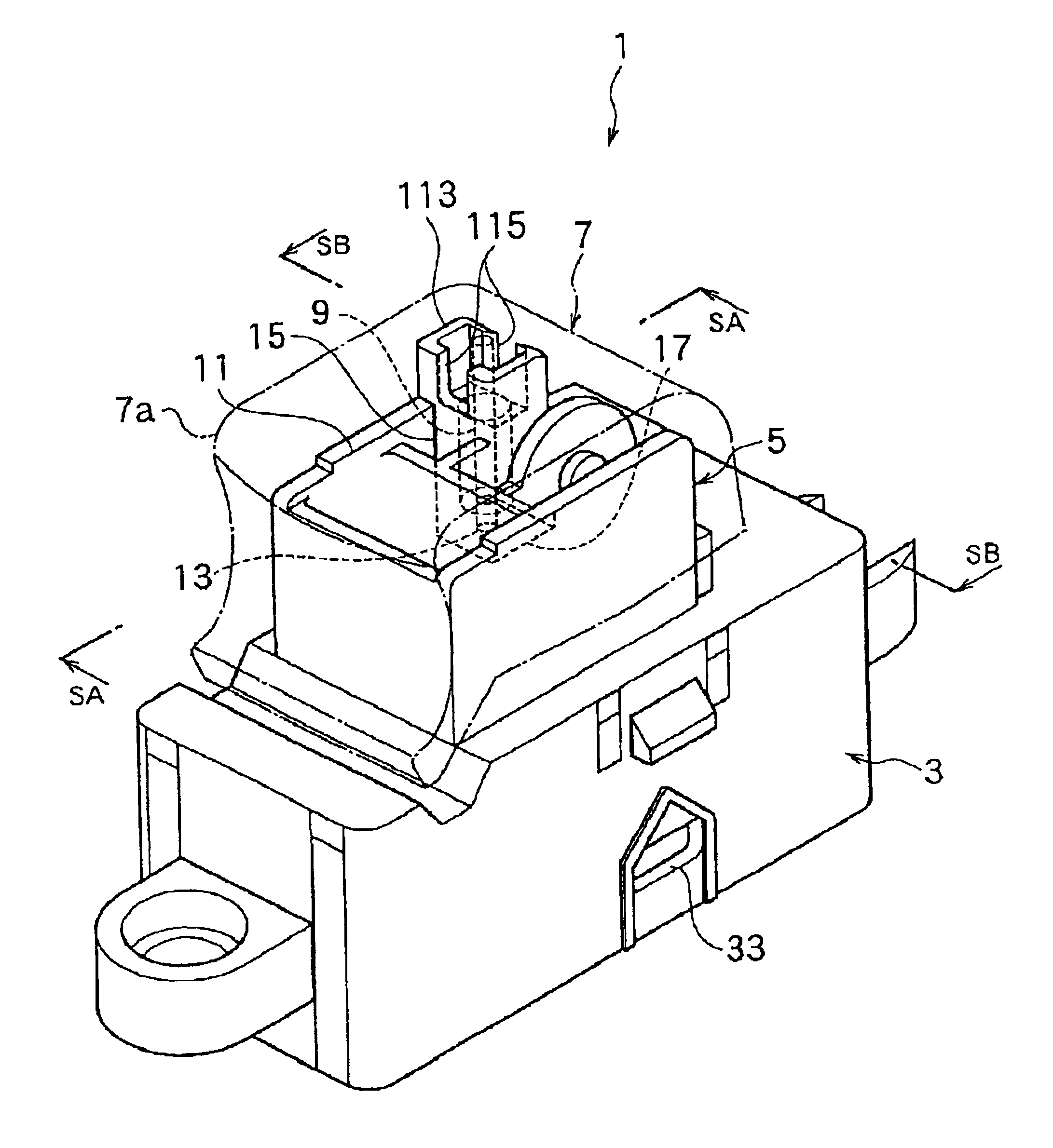
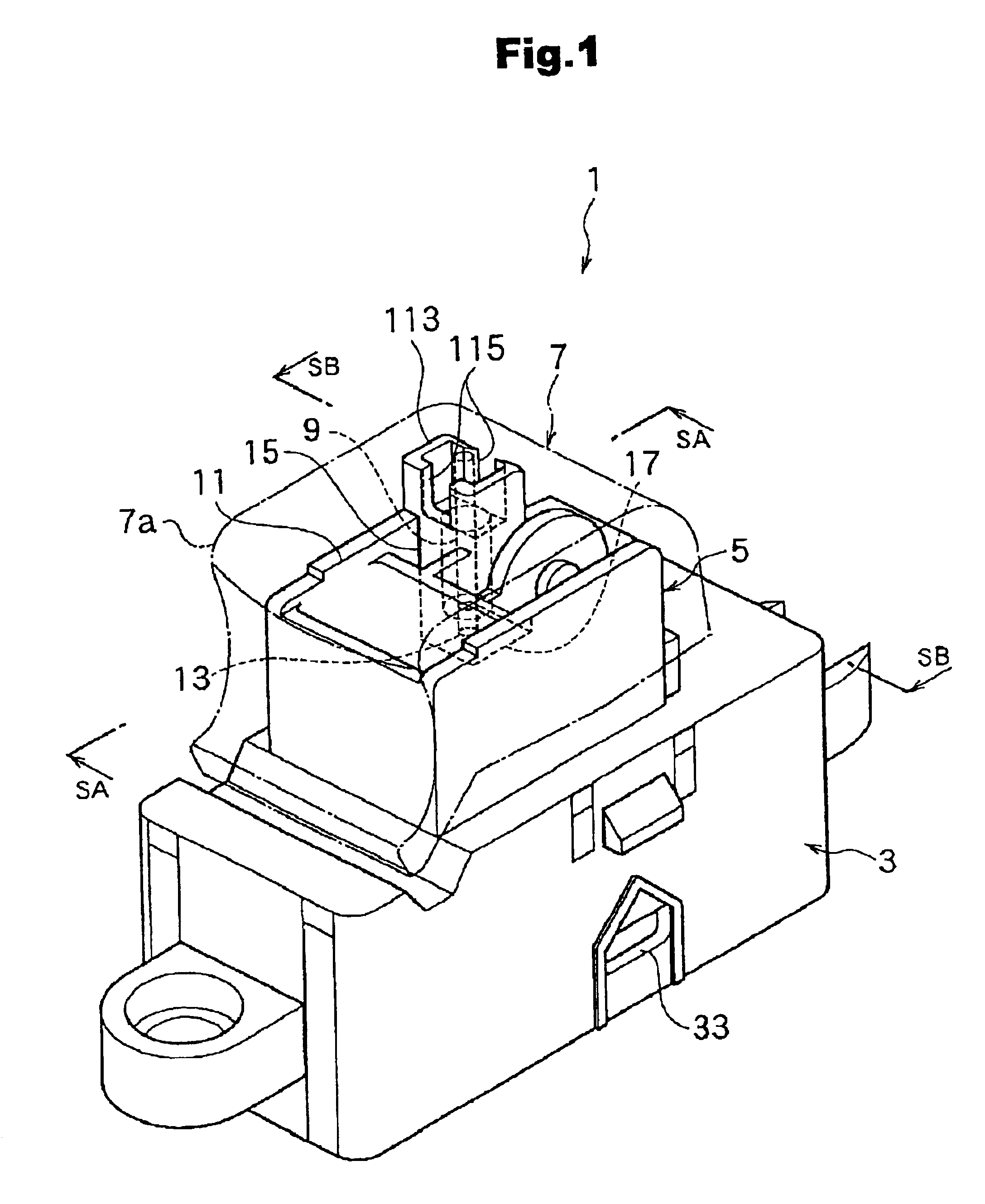
[0054]FIG. 1 shows a perspective view of a power window switch 1 for, for example, an automobile as a switch according to a first embodiment of the invention. The power window switch 1 is provided, for example, at a window of a driver seat, a front passenger seat, a rear seat or the like of an automobile. Further, the power window switch 1 is installed at an arm rest of a door or a vehicle compartment side of a door of, for example, a driver seat, a front passenger seat, a rear seat or the like of an automobile. Further, a position and a direction of a respective portion or member, mentioned later, indicates a direction in the attached drawing and upper and lower directions, left and right directions and front and rear directions are changed by the state of attaching the power window switch 1 to an automobile and are not limited to illustration. An explanation will be given of the embodiment with an arbitrary illustrated state of the attached drawing as a reference...

second embodiment

(Second Embodiment)

[0101]FIG. 14 through FIG. 16 show a second embodiment of the invention. FIG. 14 is a perspective view of a switch knob 7B according to a second embodiment, FIG. 15 is a side view of essential portions in a state in which the switch knob 7B is attached to the switch case 3 and FIG. 16 is a disassembled perspective view of essential portions. A total constitution thereof is provided with a structure similar to that of the first embodiment. That is, although not illustrated, there is provided a terminal block having a similar structure. Further, an explanation will be given by attaching the same notations to corresponding constituent portions.

[0102]According to the embodiment, there is constructed a constitution in which elastic leg portions 131a and 131b are provided as an elastic portion, a receive portion is constituted by an outer face 3a of the switch case 3 and the elastic leg portions 131a and 131b are brought into elastic contact with the outer face 3a of th...

third embodiment

(Third Embodiment)

[0119]FIG. 19 through FIG. 23 show a third embodiment of the invention. FIG. 19 is a side view of a power window switch constituting a switch according to the third embodiment of the invention, FIG. 20 is a perspective view of a periphery of a switch knob, FIG. 21 is a rear view of the periphery of the switch knob, FIG. 22 is a side view of essential portions in a state in which the switch knob is attached to a switch case and FIG. 23 is a side view of essential portions for explaining operation in the state in which the switch knob is attached to the switch case.

[0120]Further, according to the embodiment, a constitution of the inside of the switch knob or the like is constructed by a structure similar to that of the first embodiment and there is provided a terminal block having a similar structure, although not illustrated. Therefore, an explanation will be given by attaching the same notations to constituent portions in correspondence with those of first embodime...


PUM


Abstract

To provide a switch that can hold a switch knob at neutral and prevent play while reducing a number of parts. In the switch, an operating lever portion of a switch knob is inserted from an opening of a knob attaching portion provided at a switch case and the switching knob is axially supported by the knob attaching portion to be capable of operating to pivot, wherein an elastic pin portion is integrally provided to the switch knob, an engaging hole for engaging the elastic pin portion is provided to a side of the switch case, and when the switch knob is operated to pivot, the switch knob is urged to a neutral portion relative to the knob attaching portion by elastic force by deforming the elastic pin portion to the engaging hole.

Description

BACKGROUND OF THE INVENTION[0001]1. Field of the Invention[0002]The present invention relates to a switch such as a seesaw type switch, a lever type switch or the like used in a power window switch or the like.[0003]2. Description of the Related Art[0004]There is a conventional seesaw type switch as shown by, for example, FIG. 25. FIG. 25 is a sectional view in a state of attaching a switch knob, showing a neutral holding structure the switch knob.[0005]As shown by FIG. 25, according to a seesaw type switch 201, a switch knob 203 is axially supported by a knob attaching portion 207 of a switch case 205 pivotably around, for example, a pivoting center C and capable of operating pivoting movement. Therefore, when the switch knob 203 is operated to push to thereby pivot around the pivoting center C in the counterclockwise direction, power window of an automobile is operated to lower. Further, when the switch knob 203 is pulled up to thereby pivot around the pivoting center C in the clo...

Claims


Application Information

Patent Timeline
Patent Type & Authority Patents(United States)
IPC IPC(8): H01H21/24H01H21/00B61B13/00B61D27/00H01H23/30
CPCH01H21/24H01H2300/01H01H2223/004H01H2221/044
Inventor SEKI, HIROSHI
Owner NILES PARTS CO LTD
Why Eureka
Try Eureka