Winding frame and deflection yoke

a winding frame and deflection technology, applied in the field of winding frame and deflection yoke, can solve the problems of general deterioration of screen quality and failure to enhance screen quality, and achieve the effect of improving the constitution of the winding face of the winding fram

Inactive Publication Date: 2005-06-28
SAMSUNG ELECTRO MECHANICS CO LTD
View PDF4 Cites 0 Cited by
  • Summary
  • Abstract
  • Description
  • Claims
  • Application Information

AI Technical Summary

Benefits of technology

[0027]It is, therefore, an object of the present invention to provide a winding frame and a deflection yoke for improving the constitution of a winding face of a winding frame by changing the coiling density on the inside of the deflection yoke by way of resolving a problem with mis-convergence.

Problems solved by technology

Unfortunately however, when a general deflection coil is used for a deflection yoke, a phenomenon called mis-convergence occurs at the corner of the monitor screen, so the screen quality in general is deteriorated.
In result, although the characteristic of a specific part was locally improved, the entire coiling density was changed thereby, which consequently failed to enhance the screen quality.

Method used


Image

  • Winding frame and deflection yoke
  • Winding frame and deflection yoke
  • Winding frame and deflection yoke

Examples


Embodiment Construction

[0046]A preferred embodiment of the present invention will now be described with reference to the accompanying drawings. In the following description, the same drawing reference numerals are used for the same elements even in different drawings. The matters defined in the description such as a detailed construction and elements of a circuit are simply ones provided to assist in a comprehensive understanding of the invention. Thus, it is apparent that the present invention can be carried out without those defined matters. Also, well-known functions or constructions are not described in detail since they would obscure the invention in unnecessary detail.

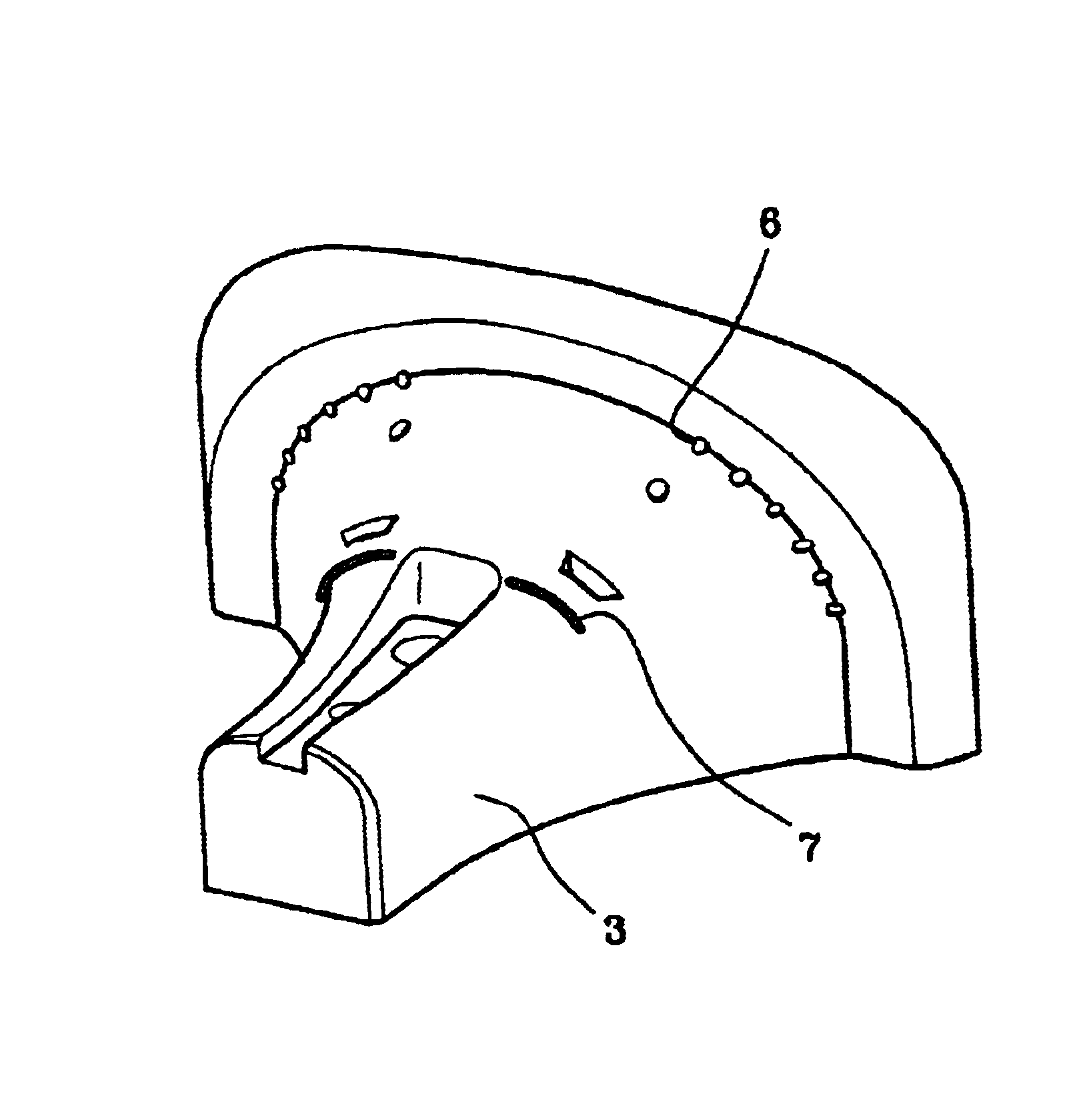
[0047]FIG. 8 is a perspective view illustrating an A-type winding frame according to a preferred embodiment of the present invention. As depicted in the drawing, there exists a winding face 3 with a curvature of a designated shape at the center of the winding frame. And, mounted on the winding face 3 is a wire position guide 7, which p...


PUM

PropertyMeasurementUnit
magnetic fieldaaaaaaaaaa
densityaaaaaaaaaa
coiling densityaaaaaaaaaa

Abstract

Disclosed is a deflection yoke to improve screen quality, including a coiling density adjustment groove formed along a vertical direction of a coil by way of increasing the coiling density at an arbitrary portion of the electric field at the internal side of the deflection coil. To this end, a winding frame is provided for winding coil around the deflection yoke, having a curvature of a designated shape at the center, in which the winding frame includes a wire position guide that projects as much as a designated width to a vertical direction of a coil to be wound around an arbitrary portion of the internal electric field for increasing a coiling density.

Description

BACKGROUND OF THE INVENTION[0001]1. Field of the Invention[0002]The present invention relates to a deflection yoke. In particular, the present invention relates to the formation of a groove for adjusting the coiling density (or the quantity of the coil to be wound on a deflection coil) to a vertical direction at an arbitrary portion of an electric field on the internal side of the deflection coil in order to improve the coiling density of the deflection coil. Further, the present invention relates to the formation of a wire position guide on the inside of the winding frame of a winding machine that winds the deflection coil.[0003]In other words, the present invention primarily aims to improve the characteristics of a deflection yoke in general by improving the constitution of a winding frame necessary for winding a deflection coil of a deflection yoke which consequently improves the properties of the deflection coil manufactured thereby.[0004]2. Description of the Related Art[0005]F...

Claims


Application Information

Patent Timeline
Patent Type & Authority Patents(United States)
IPC IPC(8): H01F7/00H01J29/76H01J9/236H01J9/00H01J29/82
CPCH01J29/762H01J29/826H01J2229/7038H01J9/236
Inventor KIM, GYOUNG SUNAMGONG, YOUNG GILLEE, CHEONG MOONHWANG, SEOK HWAN
Owner SAMSUNG ELECTRO MECHANICS CO LTD
Why Eureka
Try Eureka