Photogrammetry engine for model construction

Inactive Publication Date: 2005-06-28
KOROBKIN CARL P
View PDF10 Cites 370 Cited by
  • Summary
  • Abstract
  • Description
  • Claims
  • Application Information

AI Technical Summary

Benefits of technology

[0008]In both the consumer and merchant images, the image provider might include cues to assist the graphics system in mapping the two-dimensional object onto the three-dimensional model. For example, the user might have an object in the scene that is a rectangular prism (such as a box, dresser, refrigerator, etc) and indicate the bounds of the rectangular prism on the two-dimensional image. The graphics system can handle shapes besides rectangular prisms, such as spheres, flat rectangles, arches, boolean combinations of simple shapes, etc., limited only by the shapes represented in a shape library that forms part of the graphics system. In a typical user interface, the user selects a shape while viewing an image and then moves the shape around to approximately coincide with an object in the image.
[0009]Because the images are mapped to a geometric model, the images of the scene and the objects to be inserted do not need to be taken from the same camera position. For example, a consumer might capture an image of a room from an angle, standing at the edge of the room, but a merchant might have captured an image of a rug they are offering for sale with their camera directly over the rug. As part of the processing performed by the graphics system, it determines camera parameters, such as camera position in the geometric model, camera rotation, focal length, center of view, etc. Those parameters might already be available if th

Problems solved by technology

If the task is to construct a 3D model of a scene or object depicted in a sketch or a photograph, the use of a conventional solid modeling system can be an arduous task.
The current process typically involves first creating a 3D geometric model then tediously “cutting and pasting” textures

Method used


Image

  • Photogrammetry engine for model construction
  • Photogrammetry engine for model construction
  • Photogrammetry engine for model construction

Examples


example 1

[0314]A home furnishings merchant displays items for sale at its e-commerce web site on Internet 10. The site is enabled with the merchandising system as a SELL server node SN200. Displayed at the merchant site is the rug item depicted as image I500 of FIG. 28.

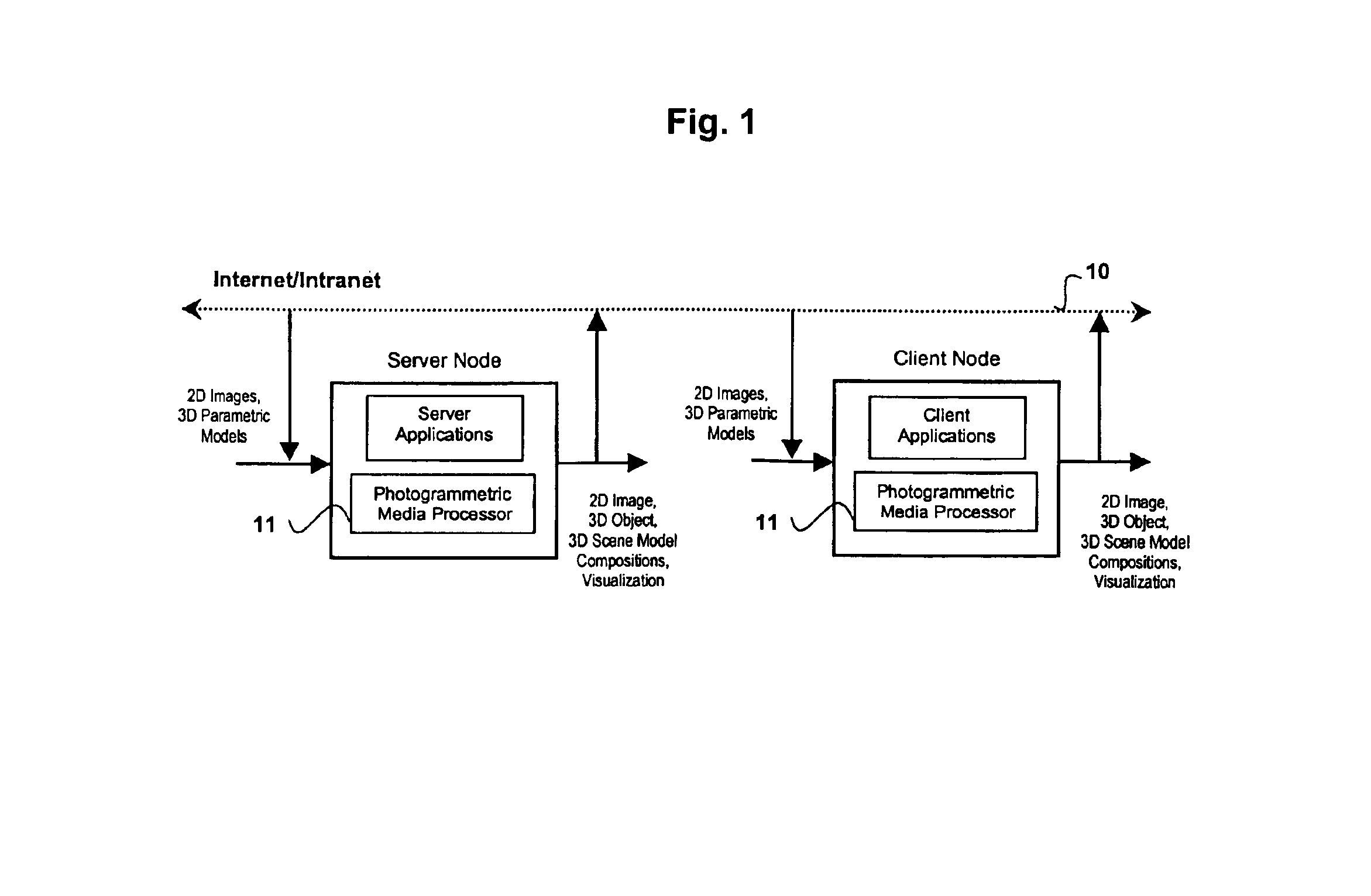
[0315]An online Internet shopper visits the merchant SELL site with interest in purchasing the rug. From the merchant site the shopper selects an option to visualize the rug in her home. This selection launches the download of a merchant-tailored client-side version of media processing engine 11 software S-PROG from the merchant SELL site to the shopper computer system on network 10. This transaction enables the shopper as a SHOP node with media processing engine 11 software components C-PROG.

[0316]The shopper seeks to visualize rug I500 in her living room depicted in FIG. 18(a) image I200. The shopper acquires image I200 with a digital camera and downloads it as user data 24. For a wider field-of-view of the living room scene...

example 2

[0320]The shopper of Example 1 wants to interactively simulate placement of the rug in various positions on the floor within the living room scene. The shopper employs the system 3D scene construction mode.

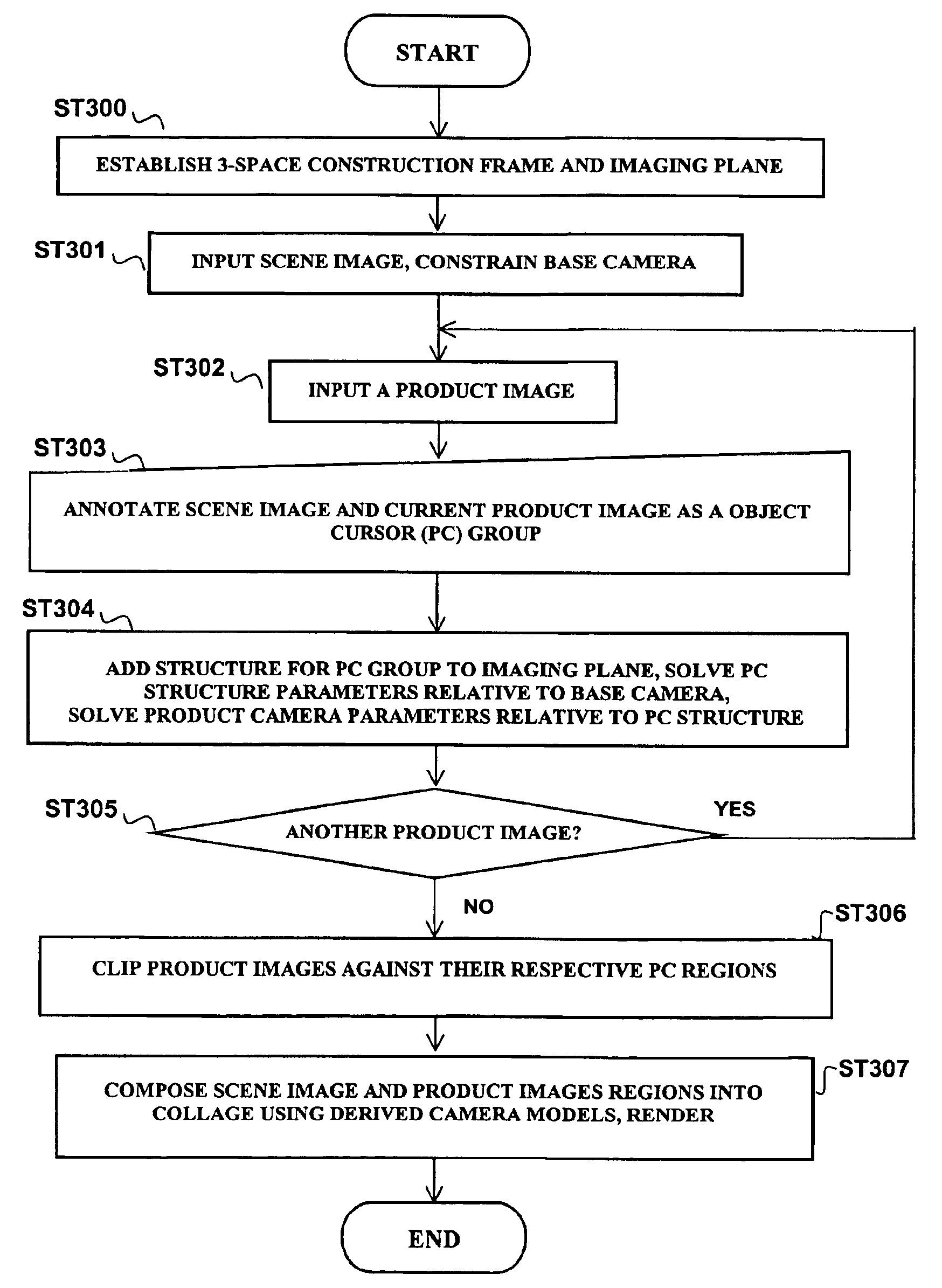
[0321]The previously described process flow of FIG. 39, with the integration of “rug” object of FIG. 28 image I500 within scene I200 of FIG. 18(a) and “true-to-scale” object insertion of FIG. 40, is executed. In her living room, the shopper measures the distance between the back wall of the room and the marble fireplace base as well as the combined width of the two right French doors. The shopper aligns PC graphic PG1 as shown in FIG. 18(c) image I200 and enters the measured values for the width and length parameters of PC structure PS20. The scene construction becomes calibrated to the true dimensions of the shopper's living room.

[0322]To place the rug on the floor of the room, the shopper selects point VF5 on the rug in image I500 and anchor point 933 on the floor in image. The ...

example 3

[0323]A shopper of home furnishings visits a merchant e-commerce web site on network 10. The merchant-site is enabled as a SELL server node SN200. The shopper selects an option at the merchant site to visualize products in his home. This selection launches the download of a merchant-tailored media processing engine 11 software S-PROG from the merchant SELL site to the shoppers' computer system on network 10. This transaction enables the shopper as a SHOP node CN100 with media processing engine 11 software C-PROG.

[0324]Displayed at the merchant site is pine storage box 91 depicted in FIG. 44 image I901. The shopper selects image I901 and the SELL node transfers an IOP and an IDP for the product to the shopper SHOP node. The IOP transferred contains the product scene graph, geometric structures, camera models, texture map imagery, and parametric shape and function parameters. The IDP contains graphic information display PUP3-30.

[0325]The shopper visits web site of another merchant on ...


PUM


Abstract

A system and methods for accessing 2D digital images and 3D geometric models over a network (preferably the Internet) and transforming and composing that media along with 2D digital image and 3D geometric model media, acquired by other means, into enhanced 2D image and 3D model representations for virtual reality visualization and simulation is disclosed. Digital images and models from a network and other sources are incorporated and manipulated through an interactive graphical user interface. A photogrammetric media processing engine automatically extracts virtual sensor (camera) and geometric models from imagery. Extracted information is used by a reconstruction processor to automatically and realistically compose images and models. A rendering system provides real-time visualization and simulation of the constructed media. A client-server processing model for deployment of the media processing engine system over a network is disclosed.

Description

CROSS-REFERENCES TO RELATED APPLICATIONS[0001]This application claims priority from U.S. Provisional Patent Application 60 / 090,749, filed Jun. 26, 1998 and incorporates that application herein by reference for all purposes.BACKGROUND OF THE INVENTION[0002]A parametric solid modeler is an approach to creating geometric models of 3D objects and scenes. Constructive Solid Geometry (CSG) and Boundary Representation (Brep) methods are two fundamental solid modeling methods. CSG uses solid primitive shapes (cones, cylinders, torus, spheres, rectangular prisms, etc.) and boolean operations (unions, subtractions, intersections) to create a solid model. A cylinder subtracted from a cube produces a hole, for instance. Brep methods start with one or more wireframe profiles, and create a solid model by extruding, sweeping, revolving or skinning these profiles. The boolean operations can also be used on the profiles themselves and the solids generated from these profiles. Solids are also created...

Claims


Application Information

Patent Timeline
IPC IPC(8): G06T3/00G06T15/00G06T17/40G06T15/20G06T17/10
CPCG06T17/10G06T15/20
Inventor KOROBKIN, CARL P.
Owner KOROBKIN CARL P
Why Eureka
Try Eureka