

Failure detection device for hydraulic motor and hydraulic drive vehicle
- Summary
- Abstract
- Description
- Claims
- Application Information
AI Technical Summary
Benefits of technology
Problems solved by technology
Method used
Image

Examples
first embodiment
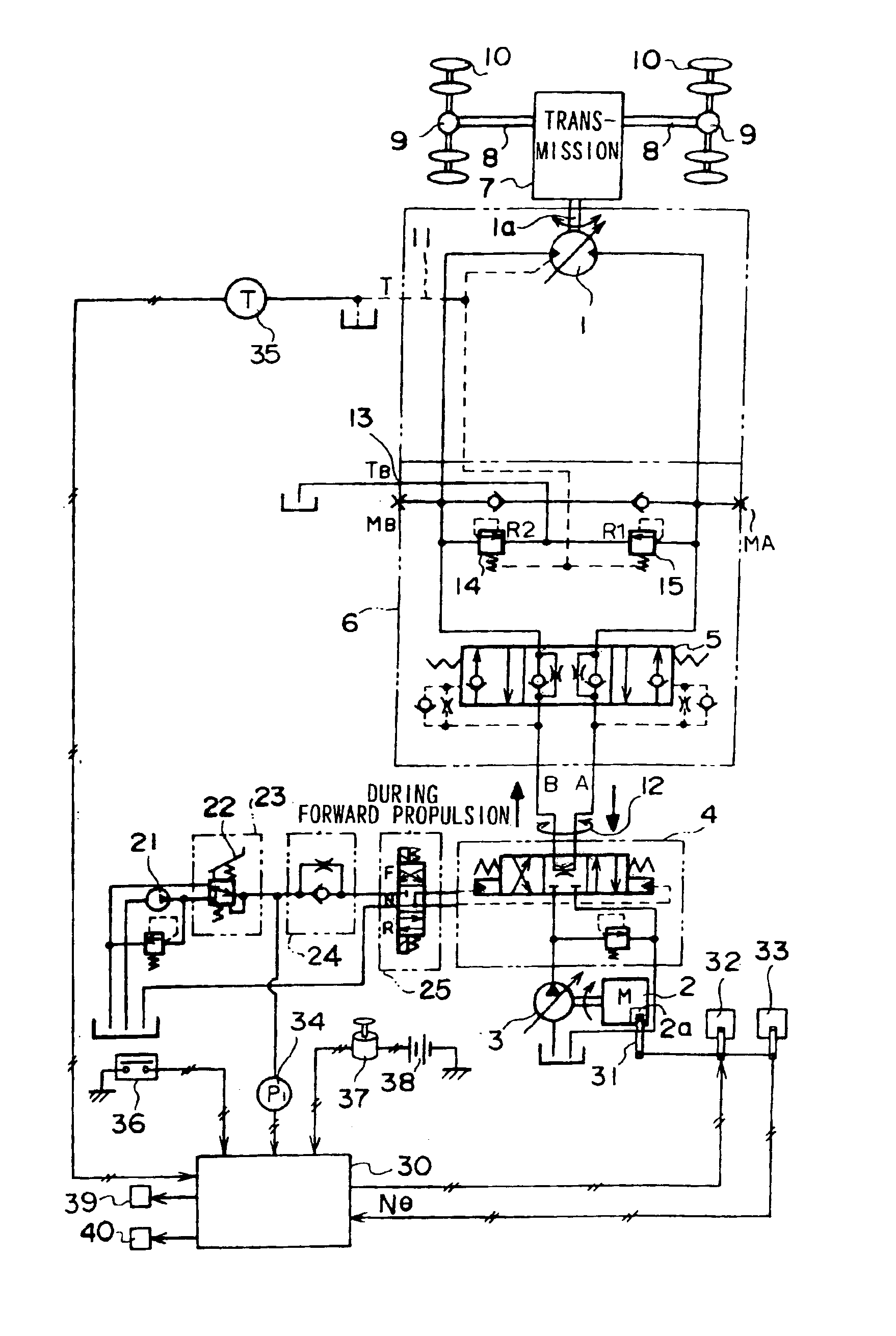
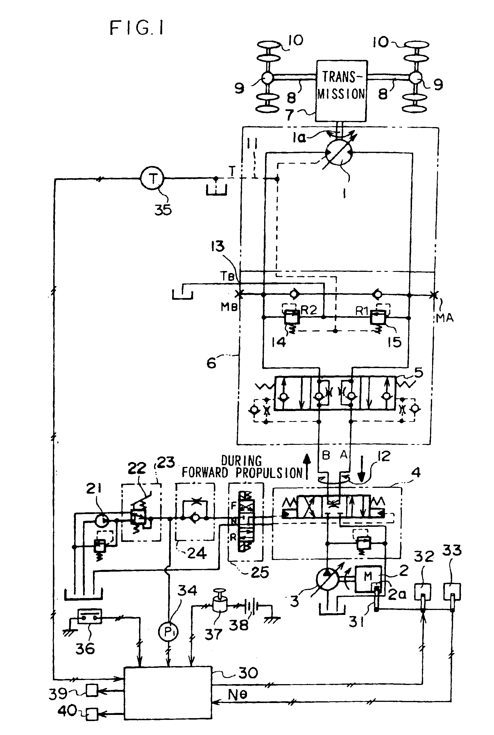
[0030]A wheeled hydraulic excavator that is equipped with a failure detection device according to the first embodiment of the present invention will now be described with reference to FIGS. 1 through 4. The wheeled hydraulic excavator comprises a wheeled undercarriage upon which an upper-structure is rotatably mounted, and a working attachment is fitted to this upper-structure. A hydraulic motor 1 for traveling which is driven by a hydraulic circuit for traveling shown in the FIG. 1 is provided in the undercarriage.
[0031]As shown in FIG. 1, hydraulic oil is discharged from a main pump 3 which is driven by an engine, the direction and flow rate of the discharged oil are controlled by a control valve 4, and then the hydraulic oil is supplied to a traveling motor 1 via a brake valve 6 with a built-in counterbalance valve 5. A transmission 7 is connected with an output shaft 1a of the traveling motor 1. The rotational speed of the traveling motor 1 is changed by the transmission 7, and ...
second embodiment
[0054]When the traveling motor 1 over-rotates or rotates at extremely high speed, friction on the sliding surfaces of the pistons 42 increases, which may cause the wear on the pistons 42, and the traveling motor 1 may be damaged. Thus, in the second embodiment, it is determined that the sign of the failure of the traveling motor 1 is detected when the rotational speed of the traveling motor 1 increases to predetermined value Na or higher. The second embodiment of the present invention will now be explained with reference to FIGS. 5 and 6. FIG. 5 is a circuit diagram showing the structure of a wheeled hydraulic excavator which is equipped with a failure detection device according to the second embodiment, and FIG. 6 schematically illustrates details of a controller 30A according to the second embodiment. It should be noted that the same reference numerals are used for elements similar to that of FIGS. 1 and 3, and the explanations will focus on the points different therefrom.
[0055]As...
third embodiment
[0057]In the third embodiment, it is determined that the sign of the failure of the traveling motor 1 is detected when cavitation has been generated. The third embodiment of the present invention will now be explained with reference to FIGS. 7 and 8. FIG. 7 is a circuit diagram showing the construction of a wheeled hydraulic excavator which is equipped with a failure detection device according to the third embodiment, and FIG. 8 schematically illustrates the structure of a controller 30B according to the third embodiment. It should be noted that the same reference numerals are used for elements similar to that of FIGS. 1 and 3, and the explanations will focus on the points different therefrom.
[0058]As shown in FIG. 7, pressure sensors 27-29 are provided at the inlet port, the outlet port and the make-up port of the traveling motor 1, respectively. These pressure sensors 27-29 each detects motor inlet pressure during normal rotation, reverse rotation and braking operation. As shown i...
PUM
 Abstract
Description
Claims
Application Information