Security reversible key and locking system

a technology of reversible keys and locking systems, applied in the field of reversible keys, can solve the problems of reducing the security of the system, reducing the security of the key, so as to achieve enhanced security and copy protection, higher security, and the effect of enhancing the permutation capacity

Inactive Publication Date: 2005-07-05
KABA SCHLIESSYST
View PDF18 Cites 10 Cited by
  • Summary
  • Abstract
  • Description
  • Claims
  • Application Information

AI Technical Summary

Benefits of technology

[0004]It is an objective of the present invention to create a security reversible key with an assigned cylinder. More specifically, it is an objective of the invention to provide a locking system with security reversible keys and assigned cylinders, which can be utilized as a world-wide unique locking system, with higher permutation capacities for any kind of application, with enhanced security and copy protection as well as with new possibilities of being in a position to separate any kind of market area and application world-wide, and whereby, without any additional space requirement on keys and cylinders, a higher security and a greater number of permutations is achieved. A further objective of the present invention is a manufacturing method for a system of this kind, which can rapidly and universally be brought into use and applied world-wide.
[0005]In accordance with the present invention, a security reversible key has an assigned cylinder, a locking system has security reversible keys with assigned cylinders, and a method is provided to manufacture such keys. With the new additional security element “blocking code”, which comprises a coded blocking groove and an assigned pair of blocking tumbler pins, without any additional space requirement on the key and in the cylinder, i.e., with the existing coding positions on the key and the existing pin rows and positions in the cylinder, an additional insertion blocking system as well as a higher number of permutations and applications are achieved. With the division into areas on the key, whereby the first area with additional security elements defines an unequivocal segmentation into independent market areas, a system is created that corresponds to the above named objective and which can be realized with the new, multi-step manufacturing process.
[0006]Especially with the new additional security element “blocking code”, which comprises a coded blocking groove and an assigned pair of blocking tumbler pins, without any additional space requirement on the key and in the cylinder, i.e., with the existing coding positions on the key and the existing pin rows and positions in the cylinder, an additional insertion blocking system as well as a higher number of permutations and applications are achieved.

Problems solved by technology

These known high-security keys and systems with high-security keys are also always limited by the space available for the coding and security functions on the key and in the cylinder.
Their manufacture calls for a central production, which limits, renders more difficult, and delays the world-wide universal application of such systems.
Also, an optimum design for installations and applications of any kind is severely restricted by this.

Method used


Image

  • Security reversible key and locking system
  • Security reversible key and locking system
  • Security reversible key and locking system

Examples


Embodiment Construction

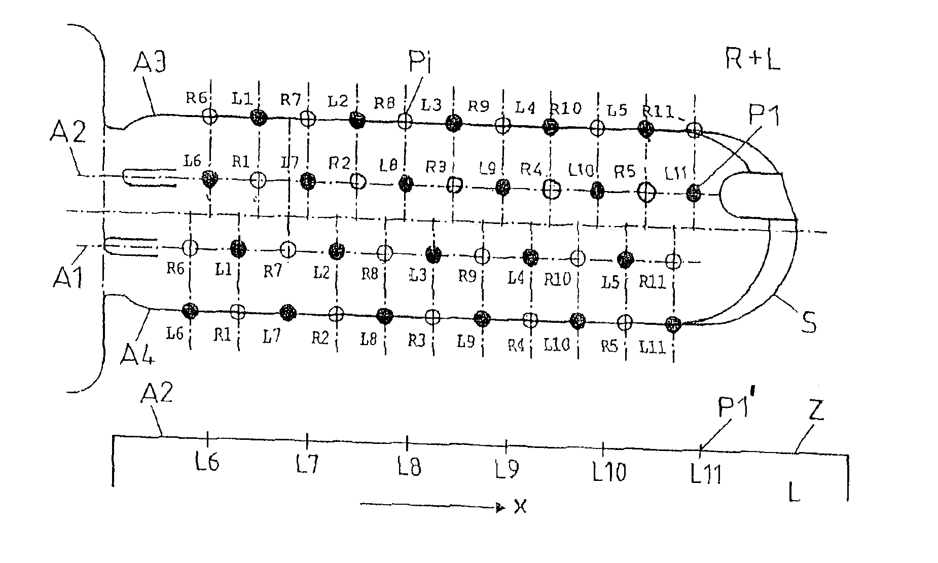
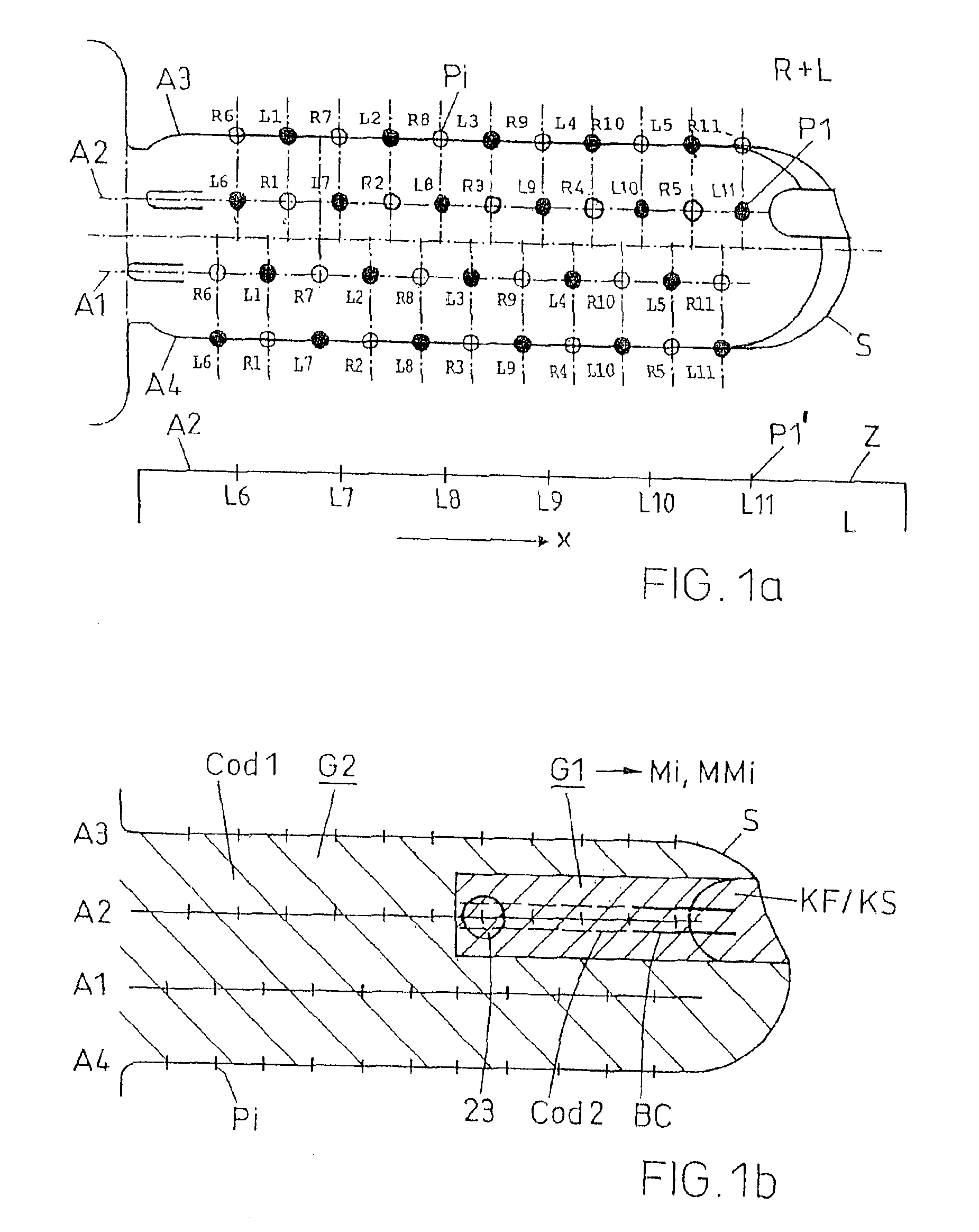
[0031]FIG. 1a, as an example, illustrates a safety turning-key S with four pin rows A1 to A4 and with 22 coding positions Pi, each one for a bore pattern left (L) and a bore pattern right (R). The coding row A2 on the key S here has the positions R1 to R5 for the bore pattern R and the positions L6 to L11 for the bore pattern L. On the keys, all positions of both bore patterns can be coded. For example, there are keys with bore pattern left, keys with bore pattern right and also keys with the two bore patterns R+L. In the assigned cylinder Z, however, for reasons of space for the pins, only every second position and, with this, only either a bore pattern R or a bore pattern L can be equipped with tumbler pins (in the same area). The first coding position P1 (=L11) on the tip of the key here corresponds to the rearmost tumbler pin position P1′ in the cylinder with respect to the direction of insertion x of the key S.

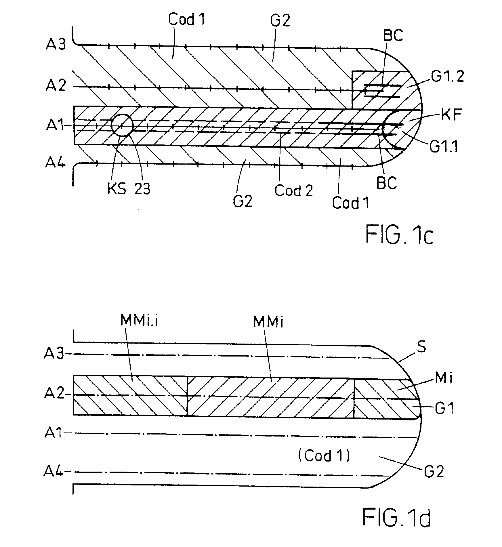
[0032]FIG. 1b illustrates the locking system in accordance with the ...


PUM


Abstract

The security reversible key with an assigned cylinder (Z) has a blocking groove (BN) with a coded blocking depth (B1, B2, B3), which runs parallel to the axis of the key (x) from the tip of the key to at least the first position (P1) of a row of tumbler pins (A2) on the key. In the assigned cylinder, at least at the rearmost coding position (P1), a pair of tumbler pins corresponding to the blocking groove (BN) with a blocking tumbler pin (BZ) and an extended blocking counter pin (BG) are foreseen, whereby the blocking counter pin (BG) impinges on the cylinder housing (10), if the blocking groove is insufficiently deep and, with this, the complete insertion of a key with an insufficiently deep blocking groove is blocked by the pair of blocking tumbler pins. Simultaneously, the blocking tumbler pin (BZ) with the counter pin (BG) at the position (P1) also serves as coding tumbler pin. In the case of the locking system with security reversible keys for locking installations at least two areas are defined, In a first area (G1) several additional security elements and a blocking code function are provided while, in the second area (G2), a more simple basic coding are foreseen. With the first area (G1), an unequivocal segmentation into independent market areas (M1, M2, M3) is defined and, with this, a world-wide unique locking system with enhanced security and applicability is created.

Description

BACKGROUND OF THE INVENTION[0001]The invention concerns a security reversible key with an assigned cylinder, a locking system with security reversible keys for locking systems, and a method for their manufacture. Such keys and locking systems are known, where the keys with a high degree of security and a correspondingly high number of possible coding permutations. The keys have at least three, and preferably at least four coding tumbler pin rows. The tumbler row pins are located on the flat sides of the key in order to make the best possible use of the available key surface, as well as the corresponding space requirement for the tumbler pin rows in the cylinder. Keys with additional security elements are also known, which once again require a certain amount of space.[0002]From U.S. Pat. No. 5,438,857, such a key is known, with an insertion blocking system as an additional security element. In the '857 key an additional control face is located on the key that, by means of an assigned...

Claims


Application Information

Patent Timeline
Patent Type & Authority Patents(United States)
IPC IPC(8): E05B17/16E05B17/00E05B19/00E05B27/00E05BE05B19/02E05B19/06E05B27/02E05B27/06E05B27/10
CPCE05B17/0004E05B17/16E05B19/0023E05B27/00Y10T70/7605Y10T70/7864Y10T70/7881Y10T70/7944Y10T70/7977
Inventor KLEINHAENI, ARNO
Owner KABA SCHLIESSYST
Why Eureka
Try Eureka