Capacitive pressure sensor

a capacitive pressure sensor and capacitive technology, applied in the direction of fluid pressure measurement, fluid pressure measurement by electric/magnetic elements, instruments, etc., can solve the problems of affecting the accuracy of measurement, and causing errors in measured pressure, so as to improve the temperature characteristic of electrostatic capacitance, reduce the strain of the substrate, and improve the effect of electrostatic capacitance capacitan

Active Publication Date: 2005-07-05
ANELVA CORP
View PDF4 Cites 10 Cited by
  • Summary
  • Abstract
  • Description
  • Claims
  • Application Information

AI Technical Summary

Benefits of technology

[0013]Then, further examination based on the above knowledge was carried out on various sensor configurations and the method for mounting a sensor chip in order to avoid the diaphragm deformation. Consequently, pressure sensors which realize reliable measurements have been completed. That is, an object of this invention is to provide a capacitive pressure sensor with a detachable sensor chip, which reduces the variation and the scatter in electrostatic capacitance due to the manner of attachment of the sensor chip. Another object of this invention is to provide a capacitive pressure sensor which realizes reliable measurements even in the case where ambient temperature varies.
[0015]Thus, the sensor chip is fixed by the force which is exerted not onto the entire sensor chip but only onto the third substrate with a pressure inlet, and hence, the diaphragm can be prevented from deformation caused by the attachment of sensor chip. This makes it possible to obtain the capacitance as designed, and moreover stable and accurate measurements over a prescribed pressure range are realized.
[0017]It is also preferable to employ a guide member to prevent the destruction of the third substrate due to excessive tightening by screws. That is, the gap between the base adaptor and the press plate by which the peripheral region of the third substrate is pressed onto the base adaptor is kept to be larger than a prescribed value. This makes it easy and safe to mount the sensor chip.
[0018]In addition, it is preferable to place a buffer member between said press plate and said third substrate. In particular, another same O-ring as being used as the sealing member is also placed as the buffer member at the symmetrical position on the opposite surface of the third substrate. The buffer member reduces the substrate strain due to the difference of thermal expansions and improves the temperature characteristic of electrostatic capacitance to carry out accurate pressure measurements.
[0019]The buffer member embodiments of this invention can reduce the strain of the third substrate which is caused by the difference of thermal expansions between the press plate and the third substrate. Therefore, an elastic material such as rubber is preferably employed and even a rigid material may be also employed so long as its friction coefficient is small.

Problems solved by technology

The pressure sensor having such a configuration is however disadvantageous because the base adaptor must be also replaced when the sensor chip is needed to be exchanged, and results in a wasteful use.
However, it has been found that the pressure sensors shown in FIGS. 8 and 9 have a disadvantage that the measurement accuracy can't be maintained since the measured pressure values change with the condition on which the sensor chip 1 is mounted.
The deformation of the diaphragm induces a significant change in the electrostatic capacitance, and hence the errors in the measured pressure are caused.
However, this operation is very complicated and requires special skills.

Method used


Image

  • Capacitive pressure sensor
  • Capacitive pressure sensor
  • Capacitive pressure sensor

Examples


embodiment 1

[0031](Embodiment 1)

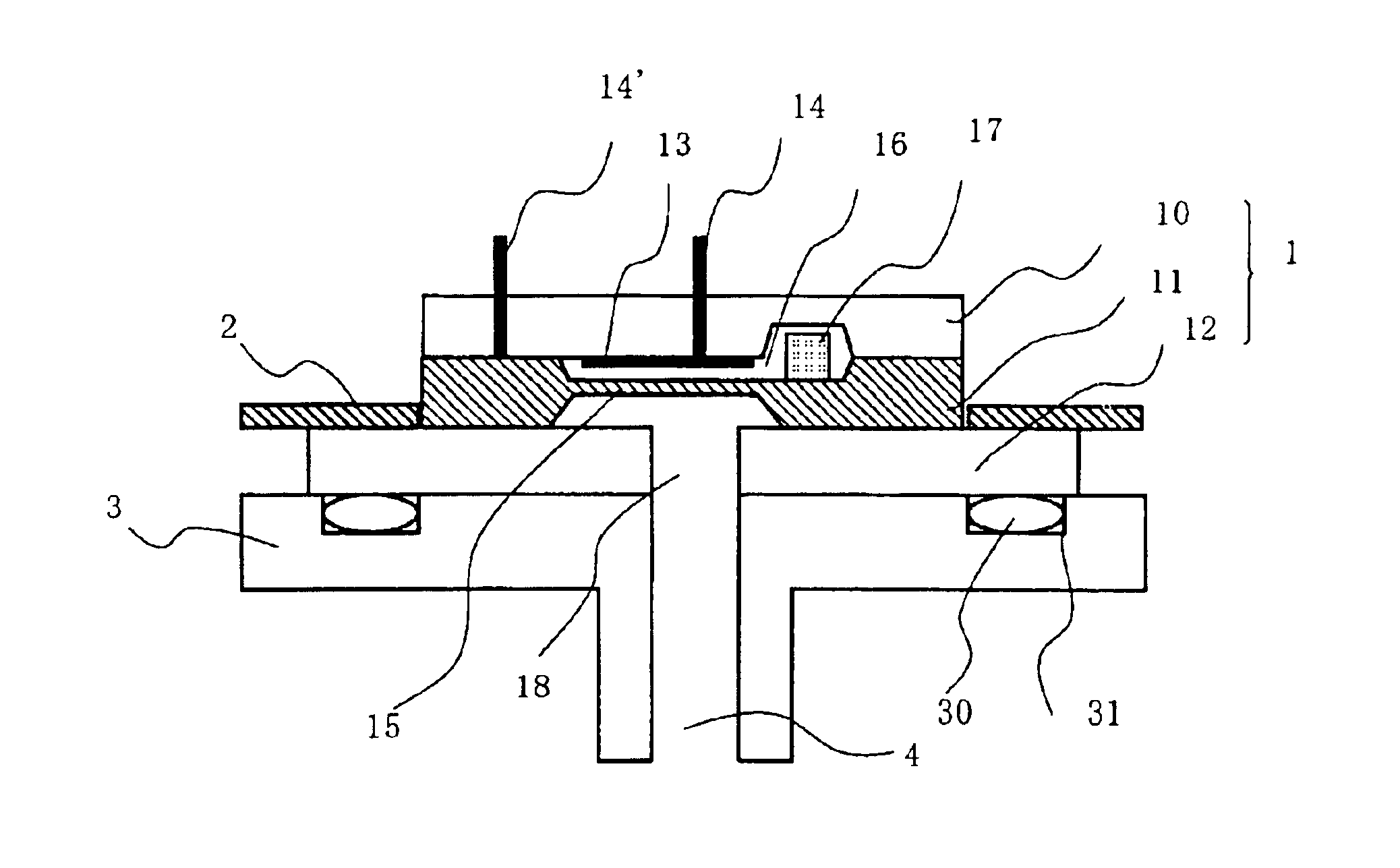
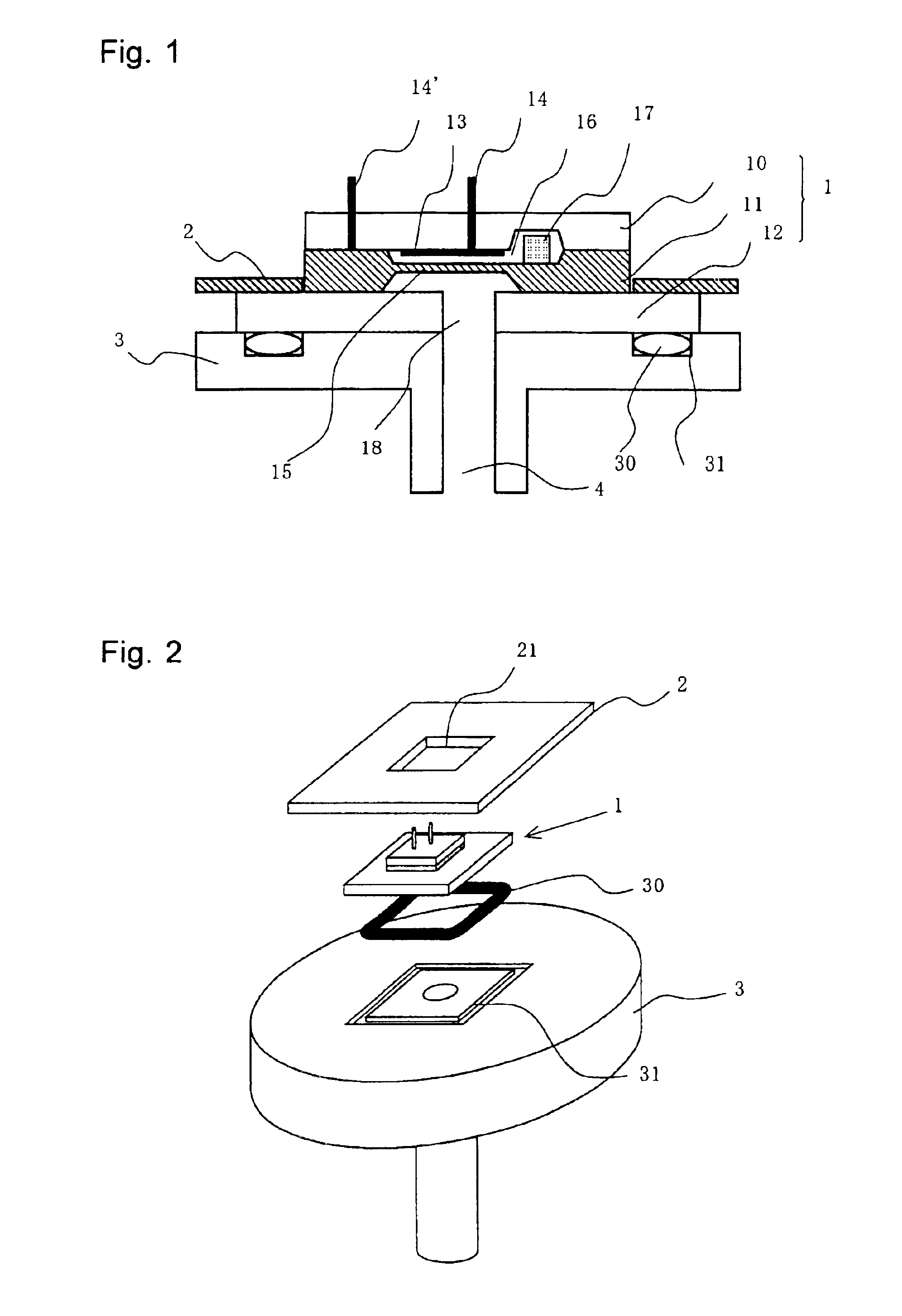
[0032]FIG. 1 is a schematic sectional view explaining one example of the capacitive pressure sensor on this invention, and FIG. 2 is an exploded view of the sensor.

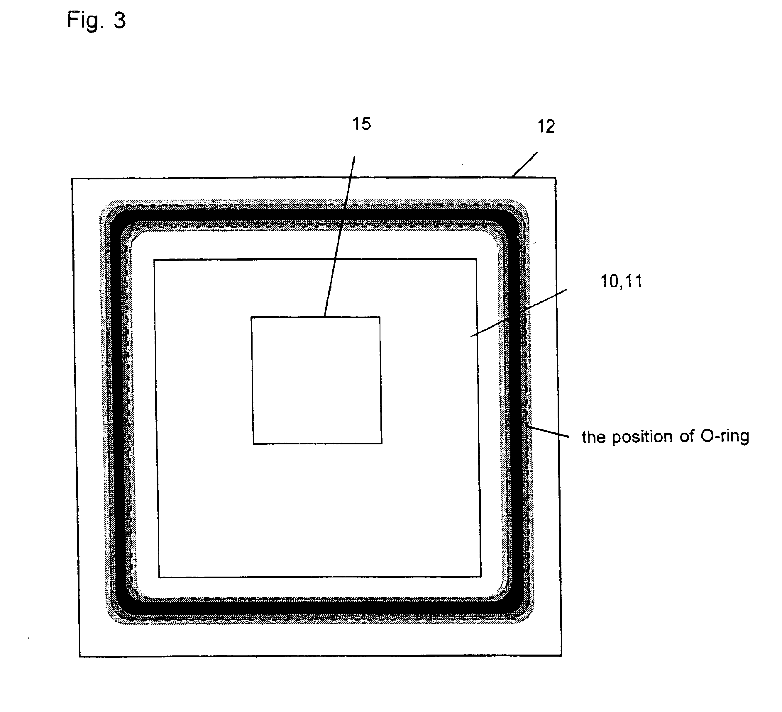
[0033]As shown in the drawings, the pressure sensor chip of this embodiment is composed of three substrates, that is, a glass substrate 10 with a fixed electrode 13 (first substrate), a silicon substrate (for example, boron-doped silicon) 11 with a diaphragm (electrode) 15 of which thickness is several microns to dozens of microns (second substrate) and a glass substrate 12 with a pressure inlet 18 (third substrate). The multi-structure is formed by bonding these three substrates. The glass substrate 12 is larger than both the glass substrate 10 and the silicon substrate 11, and the peripheral region of glass substrate 12 is protruded from the endfaces of other substrates 10, 11.

[0034]The electrical signal of the fixed electrode 13 is taken out through lead wire 14 which runs through glass substrate 10...

embodiment 2

[0045](Embodiment 2)

[0046]Next, another example of the present invention is shown in FIG. 5.

[0047]FIG. 5 is a sectional view of a pressure sensor where a guide member 32 is equipped around the sensor chip 1. By the equipment of the guide member 32, excessive force is not exerted onto the glass substrate 12, and it helps to avoid the destruction of the glass substrate and makes the mounting operation easy and safe.

embodiment 3

[0048](Embodiment 3)

[0049]As mentioned above, the pressure sensors of Embodiments 1 and 2 reduce the strain of the sensor chip which is attributed to the mounting condition, and therefore can suppress the variation and the scatter in the electrostatic capacitance. In contrast, it was found that the output signal from these sensor chips changes with the ambient temperature although the degree of change itself is very small as compared with the conventional sensors. From the experimental investigation, it was also found that temperature dependence of electrostatic capacitance increases with the deviation from the designed capacitance when the sensor chip is mounted on the base adaptor.

[0050]This may be explained as follows. Since the press plate and the base adaptor are usually made of stainless steel whose thermal expansion coefficient is larger than those of silicon and Pyrex glass, it is likely that when the sensor chip is directly pressed and fixed by the press plate, the differen...


PUM

PropertyMeasurementUnit
thicknessaaaaaaaaaa
degree of displacementaaaaaaaaaa
pressureaaaaaaaaaa

Abstract

A pressure sensor includes a capacitive pressure sensor chip mounted with the intervention of a sealing member on a base adaptor so as to be detachable. The sensor chip being constructed in a manner that a second substrate with a diaphragm electrode is placed between a first substrate with a fixed electrode and a third substrate with a pressure inlet and is bonded to the first and the third substrate so as to overlap the fixed electrode, the diaphragm electrode and the pressure inlet with a prescribed gap between the fixed electrode and the diaphragm electrode. Moreover, the third substrate is larger than the second substrate to make place which extends outside the second substrate and plays a role as a sealing surface to be in contact with the sealing member, and the sealing surface is pressed to the base adaptor with the intervention of the sealing member.

Description

CROSS-REFERENCE TO RELATED APPLICATIONS[0001]The present application claims the priority of JP 2002-368867 filed in Japan Dec. 19, 2002,the entire contents of which are incorporated herein by reference.BACKGROUND OF THE INVENTION[0002]1. Field of the Invention[0003]The present invention relates to a capacitive pressure sensor and, more particularly, to a high accuracy pressure sensor which enables exchange of a multi-structural sensor chip.[0004]2. Description of Related Art[0005]In recent years, the manufacturing techniques of semiconductor devices have been applied to the production of structural components which are essentially sub-millimeter-sized. This technology is called microelectromechanical systems (MEMS) and is widely used to fabricate light and small actuators, sensors and the like in many technical fields. Capacitive pressure sensors can also be produced by MEMS technology, and one example of them is described in JP2001-201417A.[0006]A conventional capacitive pressure s...

Claims


Application Information

Patent Timeline
Patent Type & Authority Patents(United States)
IPC IPC(8): G01L9/12H01L33/00G01L9/00
CPCG01L9/0073
Inventor MIYASHITA, HARUZO
Owner ANELVA CORP
Why Eureka
Try Eureka