Electronically controlled throttle control apparatus

a technology of electronic control and throttle control, which is applied in the direction of valve details, valve arrangements, machines/engines, etc., can solve the problems of difficult to use the same components in the gear case, and achieve the effect of reducing cost, reducing the number of components, and reducing the number of required gear case variations

Active Publication Date: 2005-07-05
DENSO CORP
View PDF18 Cites 22 Cited by
  • Summary
  • Abstract
  • Description
  • Claims
  • Application Information

AI Technical Summary

Benefits of technology

[0011]According to the present invention, in a gear case which is integrally formed on the outer wall surface of a throttle body, at least a throttle shaft, an intermediate shaft and a motor shaft are in alignment with each other. Hence, even when the rotation direction of the drive motor and the valve-side gear differs among models, the components inside the gear case can be used as common components for presumably all models. Therefore, the components inside the gear case integrally formed on the outer wall surface of the throttle body can be used as common components just by changing the bore inside diameter depending on the engine displacement and the model, namely as far as the bore diameter is identical. When the throttle body bore diameter is identical, the number of required gear case variations (in shape and type) can be almost halved. Thus, for presumably all models, it is possible to decrease the number of components and reduce cost.

Problems solved by technology

However, even when the bore inside diameter of the throttle body is identical, it has been difficult to commonly use the same components to be housed in the gear case integrally formed on the outer wall surface of the throttle body, regardless of the engine displacement or car model, for the following reasons.

Method used


Image

  • Electronically controlled throttle control apparatus
  • Electronically controlled throttle control apparatus
  • Electronically controlled throttle control apparatus

Examples


first embodiment

[0025][First Embodiment]

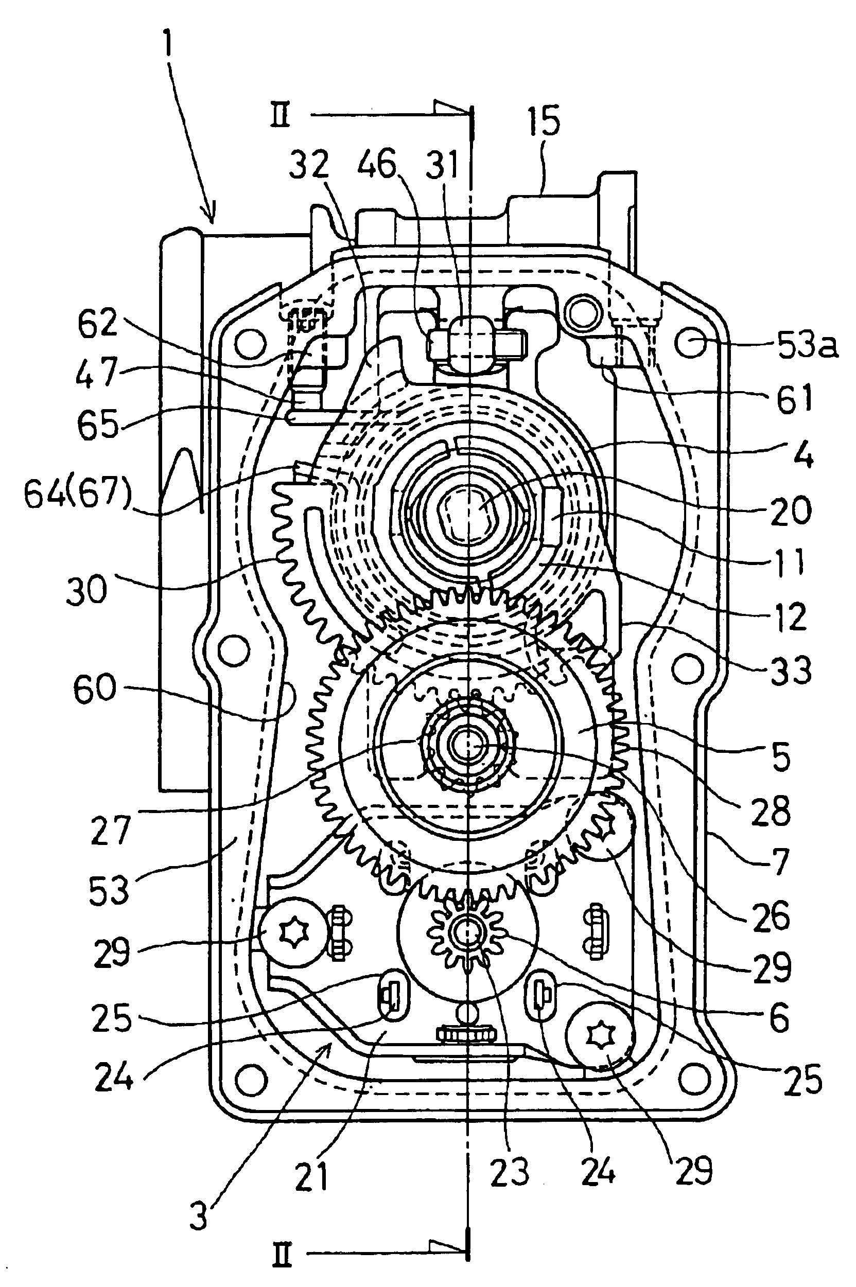
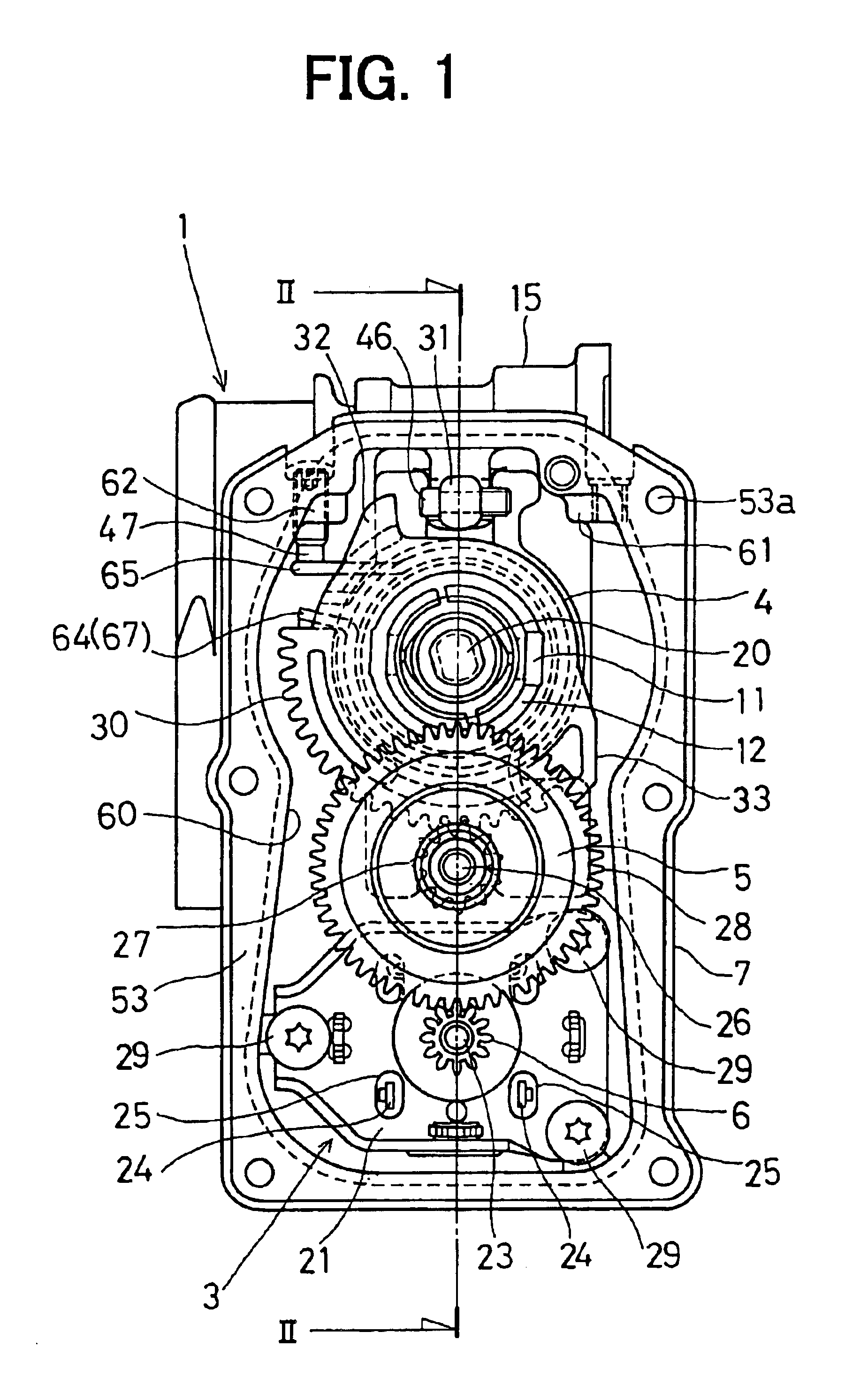
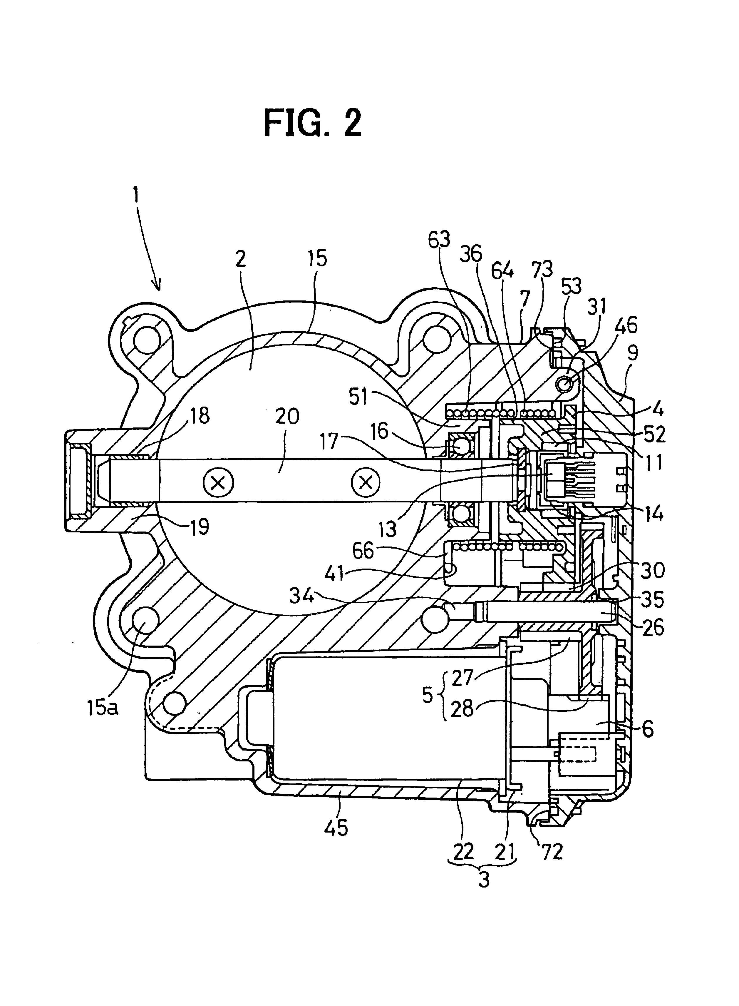
[0026]The electronically controlled throttle control apparatus in the first embodiment is an intake air control apparatus for an internal combustion engine which includes, as shown in FIG. 1 and FIG. 2 in particular: a throttle body 1 which constitutes an intake air passage to an internal combustion engine; a throttle valve 2 which is rotatably supported inside the bore of the throttle body 1; a drive motor 3 as an actuator which opens / closes the throttle valve 2; a reduction gear as a transmission system which transmits the torque of the drive motor 3 to the throttle valve 2; an actuator case which houses the drive motor 3 and the reduction gear; a coil spring fitted between the throttle body 1 and the reduction gear; and an engine control unit (ECU) which electronically controls the drive motor 3.

[0027]In this embodiment, the actuator case is composed of: a gear case (gear housing, case body) 7 and a gear cover (sensor cover, cover) 9. The gear case 7 has a...

second embodiment

[0069][Second Embodiment]

[0070]As shown in FIGS. 6, 7, 8A and 8B, around the opening side end of the gear cover 9 in this embodiment, there is an eaves or collar type joint end face (portion to be attached) 73 which circularly surrounds the concave (externally convex) gear housing 70 housing one end of the reduction gear. In this joint end face 73 on the gear cover side, there is a loop groove 72 which is recessed (concave) from the surrounding joint end face 73 by a specific amount.

[0071]Around the opening side end of the gear case 7 integrally formed on the bore wall portion 15 of the throttle body 1, there is an eaves or collar type joint end face (holder) 53 which circularly surrounds the concave gear housing 60 housing the other end of the reduction gear. In the joint end face 53 on the throttle body 1 side (gear case 7 side), there are a plurality of through holes 54 to 57 which connect the inside of the gear case 7 to the outside of the gear case 7 (gear cover 9) through the ...

third embodiment

[0076][Third Embodiment]

[0077]In this embodiment, as opposed to the second embodiment, there are no longer primary and secondary through holes 54 to 57 in the joint end face 53 of the throttle body 1 (gear case 7). Instead, as shown in FIGS. 9, 10A and 10B, a loop sealing material (elastic sealant, gasket, or rubber packing) 10 is inserted into the loop groove 72 made in the joint end face 73 of the gear cover 9 in order to prevent water from getting into the gear housings 60 and 70 located between the gear case 7 and gear cover 9.

[0078]Adopting the throttle body 1 of a waterproof structure that the loop sealing material 10 is inserted between the joint end face 53 of the gear case 7 and the joint end face 73 of the gear cover 9 ensures that water does not get into the actuator case (composed of the gear case 7 and gear cover 9). This prevents malfunctioning of the reduction gear and the drive motor 3 and also poor insulation between the two motor feeding terminals 24 and the two mo...


PUM


Abstract

In a gear case of a throttle body, a valve gear is fixed to one end of a throttle shaft, an intermediate reduction gear is rotatable around an intermediate shaft, a pinion gear is fixed to a motor shaft of a drive motor, and a full close position stopper is provided for defining the full close position of a throttle valve. Those are provided all in alignment with the longitudinal centerline of the gear case. For car models where the throttle body bore inside diameter is identical but the rotation direction of the drive motor differs, only some components in the gear case need be replaced and the other components in the gear case can be used as common components.

Description

CROSS REFERENCE TO RELATED APPLICATION[0001]This application is based on and incorporates herein by reference Japanese Patent Application No. 2002-311140 filed on Oct. 25, 2002.FIELD OF THE INVENTION[0002]The present invention relates to an electronically controlled throttle control apparatus which controls the opening degree of a throttle valve by means of a drive motor to control the flow rate of intake air which flows through the bore of the throttle body into an internal combustion engine. In particular, the present invention relates to an electronically controlled throttle control apparatus which makes it possible to use, as common components, a gear case and a gear cover which house motor torque transmission system components such as a reduction gear and other components.BACKGROUND OF THE INVENTION[0003]An electronically controlled throttle control apparatus has a throttle valve to open and close the bore of throttle body by the torque of a drive motor shaft, and an engine con...

Claims


Application Information

Patent Timeline
Patent Type & Authority Patents(United States)
IPC IPC(8): F02D11/10F02D9/02F02D9/10
CPCF02D9/1065F02D11/10F02D9/1035
Inventor OZEKI, NAOMIMIYAZAKI, SHINSUKETORII, KATSUYAARAI, MASATO
Owner DENSO CORP
Why Eureka
Try Eureka