
Smoke guide structure for kitchen hood

a technology for guiding structure and smoke path, which is applied in the direction of domestic stoves or ranges, lighting and heating apparatus, heating types, etc. it can solve the problems of contaminating the cooking food or the area in the kitchen, and no means to accumulate waste grease produced in the smoke path, so as to prevent a leakage of waste grease

Inactive Publication Date: 2005-07-05
CHIANG PI TANG
View PDF5 Cites 11 Cited by
  • Summary
  • Abstract
  • Description
  • Claims
  • Application Information

AI Technical Summary

Benefits of technology

[0007]The present invention has been accomplished under the circumstances in view. It is therefore the main object of the present invention to provide a smoke guide structure, which enables waste smoke to be effectively expelled to the outside of the kitchen and, prevents a leakage of waste grease.
[0009]To achieve these objects of the present invention, the smoke guide structure comprises an outer shell mounted inside a housing of the kitchen hood, an inner shell mounted inside the outer shell, an air path defined between the outer shell and the inner shell and connected to an air inlet of an air buffer of the kitchen hood, and a grease trap fastened to an orifice of the air path and adapted to accumulate waste grease produced in the air path. The inner shell accumulates smoke produced during cooking, enabling accumulated smoke to be sucked into the air buffer through the air path and then quickly expelled to the outside of the kitchen subject to the operation of a fan and fan motor assembly in the air buffer of the kitchen hood. Waste grease produced in the air path during cooking flows along the peripheral wall of the air path to the grease trap, preventing a leakage of waste grease.

Problems solved by technology

However, these designs provide no means to accumulate waste grease produced in the smoke path.
When waste grease produced in the smoke path after a long use of the kitchen hood, it flows along the peripheral wall of the smoke path and then drops from the bottom side of the kitchen hood to contaminate the cooking food or the area in the kitchen.

Method used


Image

  • Smoke guide structure for kitchen hood
  • Smoke guide structure for kitchen hood
  • Smoke guide structure for kitchen hood

Examples


Embodiment Construction

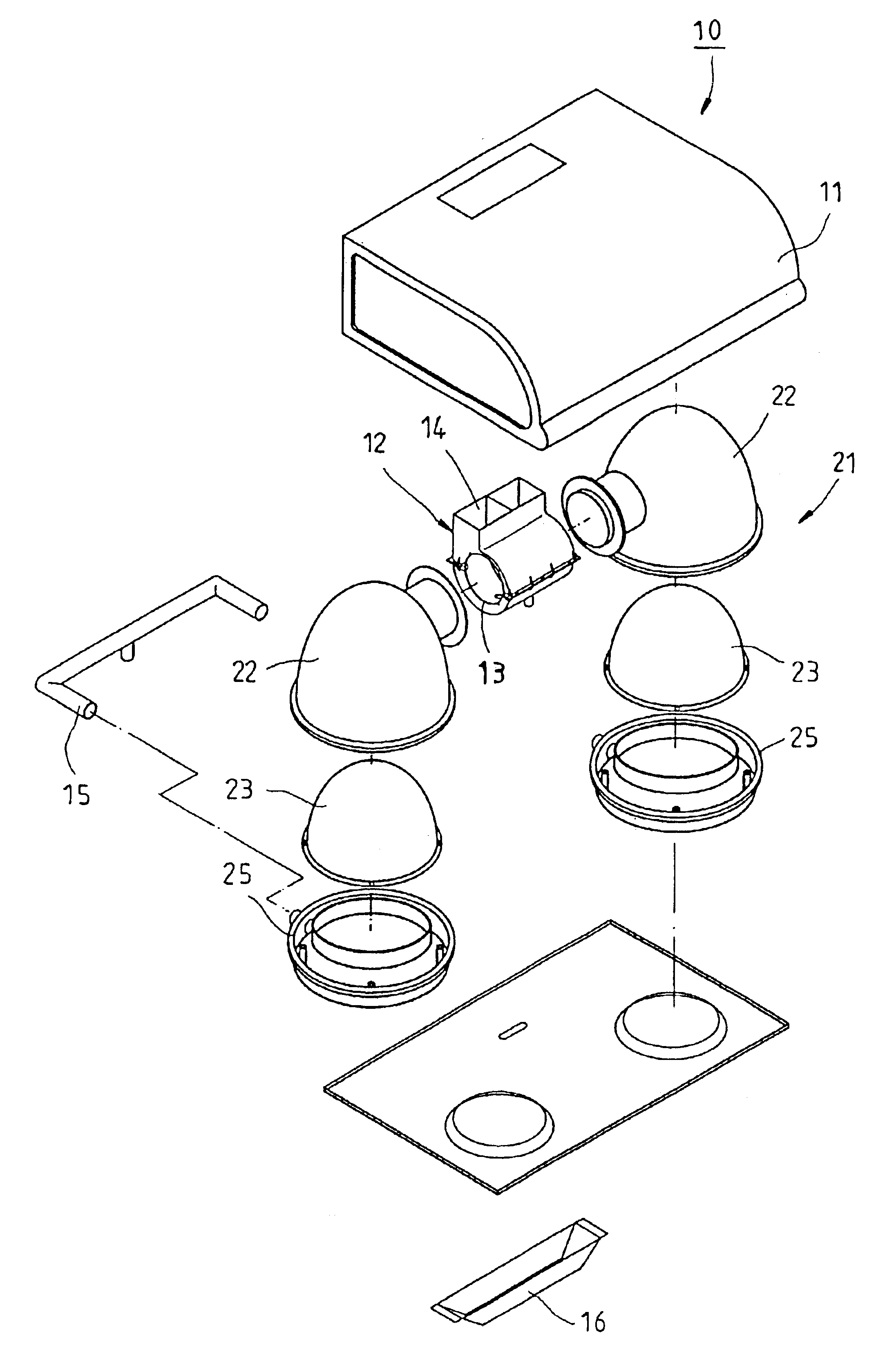
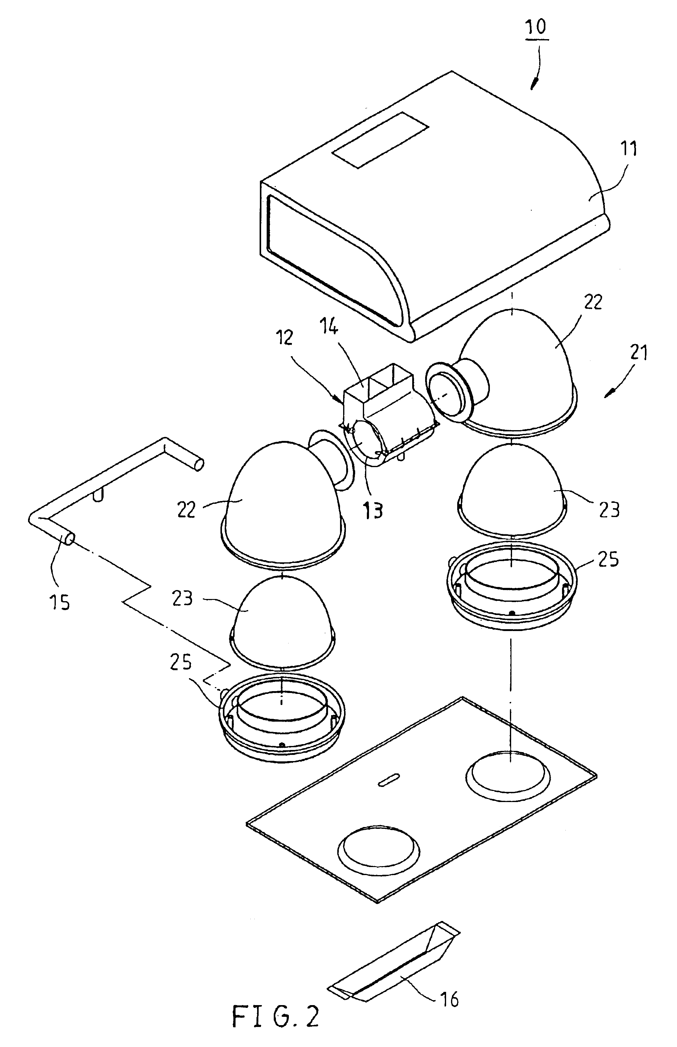
[0018]As shown in FIGS. 2-4, a kitchen hood 10 is shown comprising a housing 11, an air buffer 12 provided inside the housing 11, the air buffer 12 having an air inlet 13 and an air outlet 14, a fan and a fan motor (not shown) provided inside the air buffer 12 and operated to draw off smoke produced during cooking, and at least one, for example, two smoke guides 21 adapted to guide smoke produced during cooking into the air inlet 13. The smoke guides 21 each are comprised of an outer shell 22, an inner shell 23, and a grease trap 25.

[0019]The outer shell 22 is a smoothly arched hollow shell mounted inside the housing 11. The inner shell 23 is substantially similar to the shape of the outer shell 22 and mounted inside the outer shell 22, defining with the outer shell 22 a air path 24 in air communication with the air inlet 13 of the air buffer 12 for enabling the air inside the air path 24 to be expelled to the outside through the air outlet 14 of the air buffer 12 subject to the act...


PUM


Abstract

A smoke guide structure used in a kitchen hood having a housing, an air buffer with an air inlet and an air outlet provided inside the housing, and a fan and fan motor assembly provided inside the air buffer and adapted to draw off smoke produced during cooking is disclosed to include an outer shell mounted inside the housing, an inner shell mounted inside the outer shell, an air path defined between the outer shell and the inner shell and connected to the air inlet of the air buffer, and a grease trap fastened to an orifice of the air path and adapted to accumulate waste grease produced in the air path.

Description

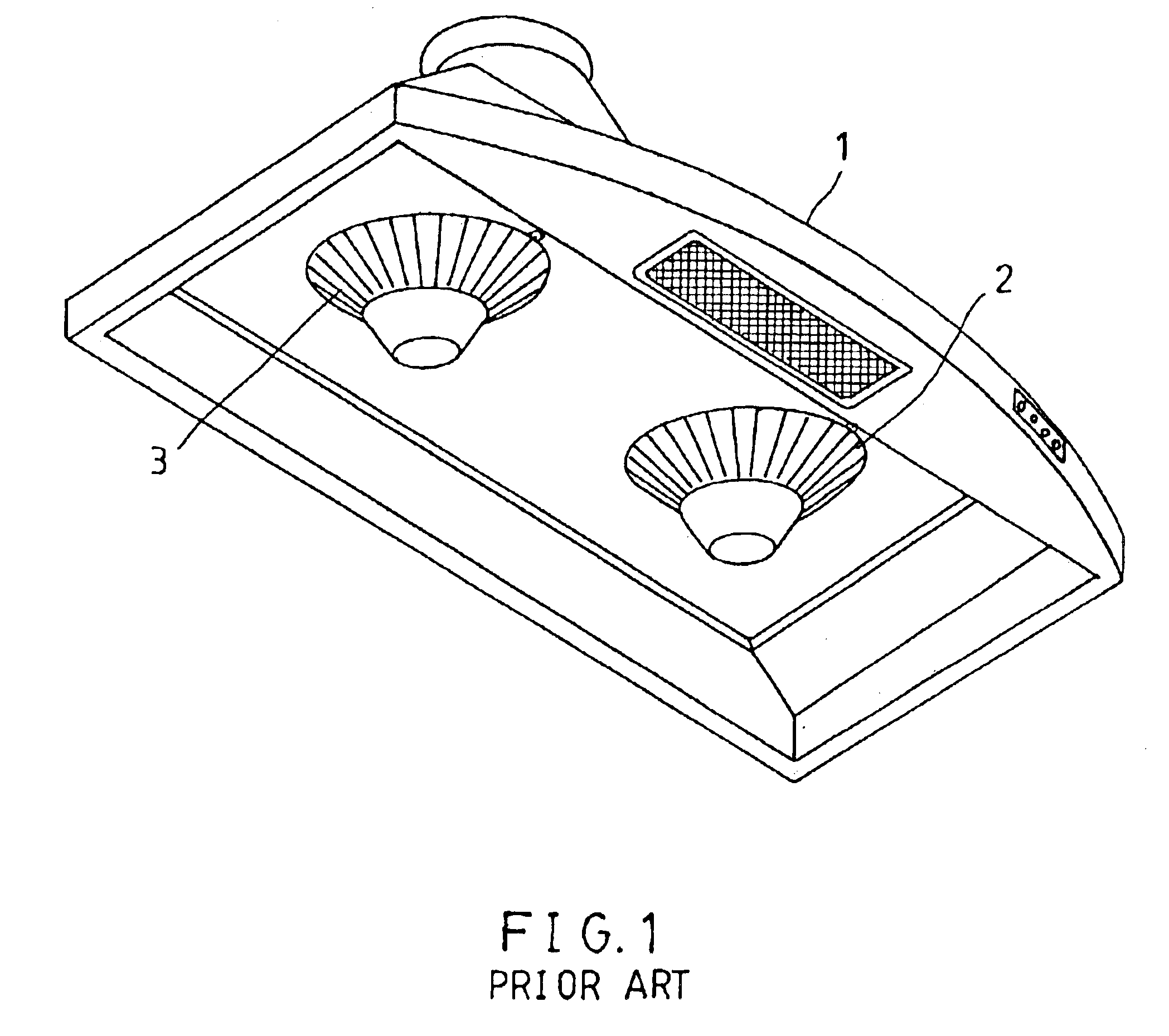
BACKGROUND OF THE INVENTION[0001]1. Field of the Invention[0002]The present invention relates generally to kitchen hoods, and more particularly to the smoke guide structure for kitchen hood.[0003]2. Description of the Related Art[0004]A regular kitchen hood 1, as shown in FIG. 1, has two circular smoke inlets 2 and 3 for sucking in smoke produced during cooking. Because smoke produced during cooking does not flow vertically upwards toward the smoke inlets 2 and 3, a part of the smoke dissipates without entering the smoke inlets 2 and 3.[0005]In order to eliminate the aforesaid problem, high-efficiency kitchen hoods have been continuously developed. Taiwan Utility Model Patent Publication No. 36912, entitled “Improved structure of smoke guide for kitchen hood”, uses a wind guide to change the angle of the smoke path, and to further achieve the object of reducing the production of noises and smoothening the air path. Taiwan Utility Model Patent Publication No. 376141, entitled “Improv...

Claims


Application Information

Patent Timeline
Patent Type & Authority Patents(United States)
IPC IPC(8): F24C15/20
CPCF24C15/20
Inventor CHIANG, PI-TANG
Owner CHIANG PI TANG
Learn More