Apparatus for dispensing liquids and solids

a technology for liquids and apparatuses, applied in the direction of fluid pressure control, process and machine control, instruments, etc., can solve the problem that the nozzle does not directly control the pump

Inactive Publication Date: 2005-07-05
FLUID RES
View PDF41 Cites 35 Cited by
  • Summary
  • Abstract
  • Description
  • Claims
  • Application Information

AI Technical Summary

Benefits of technology

[0018]In a seventh separate aspect of the present invention, a timer cooperates with a signal generator in a pumping system to provide a warning when the material in the system is approaching set up such that it cannot be driven through the system. Where a curable composition is being pumped and mixed, it will set or harden in a nonflowable state. Avoidance of this condition within the dispensing equipment is advantageous.

Problems solved by technology

The nozzle does not directly control the pump.

Method used


Image

  • Apparatus for dispensing liquids and solids
  • Apparatus for dispensing liquids and solids
  • Apparatus for dispensing liquids and solids

Examples


Embodiment Construction

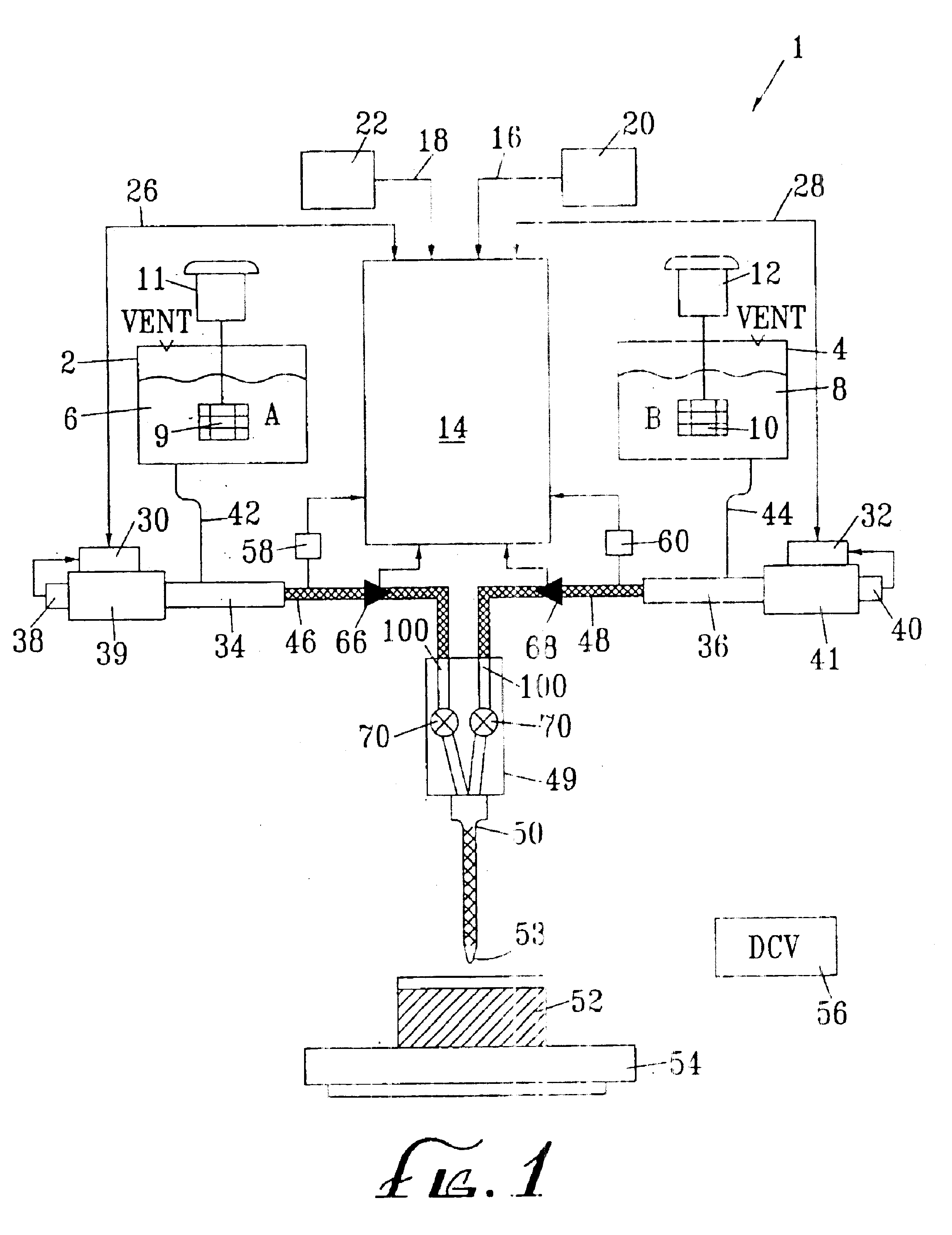
[0057]FIG. 1 illustrates a block diagram of a dispensing system 1 which dispenses a single or plural component fluid. In FIG. 1, the dispensing system 1 has a plurality of vats 2, 4, each of which holds a fluid 6, 8 that is a constituent material of the desired final product. Agitators9, 10 stir the fluids 6, 8 in order to maintain the fluids as homogeneously as possible. The dispensing system 1 has a master control unit 14 which may be a CPU, microprocessor, microcontroller, arithmetic logic unit, ASIC, field programmable gate array, or other logic control circuit. The master control unit 14 receives data and commands via data interconnects 16, 18 from a user input device 20 and / or a programming input device 22. The user input device 20 may be a keypad, buttons, switches, barcode reader, or other input device.

[0058]Depending on the input, the master control unit 14 controls various aspects of the dispensing system 1. For example, the master control unit 14 has lines 26, 28 for tran...


PUM

PropertyMeasurementUnit
voltagesaaaaaaaaaa
speedaaaaaaaaaa
proportional speedsaaaaaaaaaa

Abstract

A system for metering and dispensing single and plural component liquids and solids as described herein. The dispensing system has a microprocessor-based control system and progressive cavity pumps which provide a very accurate control of component ratios, shot sizes, flow rates and dispense durations. The system has numerous feedback components for accurately controlling the pressure, flow rates, fluid levels and amounts of fluids dispensed. Where a valved nozzle is used, the pressure in the flow system is used to control the pumps rather than the valve. Such a system may be used as a sprayer with compressed air added. Drum rams are associated with the supply drums and the progressive cavity pumps may be placed on the drum ram. Maintenance of a steady state in the system is accomplished with back and forth movement of the pump, with compensation for pressure changes. Absolute rotational position of the pump can be monitored when a set pressure is maintained, to diagnose system conditions. A high flow system uses ball valves and a releasably coupled manifold. A mold charging system uses pressure to control the pumps which are cycled on and off to avoid overpressurizing the mold. The rate of pressure increase is used to control the rate of flow from the pumps as the mold approaches completion of the charge, again to avoid overpressurizing the mold. A signal controlled by a timer can indicate elapsed time as a warning that material within the mixer conduit is hardening to a condition such that flow cannot be reinitiated.

Description

[0001]This is a divisional application of U.S. patent application Ser. No. 09 / 741,356, filed Dec. 19, 2000 now U.S. Pat. No. 6,675,988, which is a divisional application of U.S. patent application Ser. No. 09 / 451,411, filed Nov. 30, 1999, which is U.S. Pat. No. 6,161,723, issuing Dec. 1, 2000, which is a divisional application of U.S. patent application Ser. No. 09 / 032,404, filed Feb. 27, 1998, which is U.S. Pat. No. 5,992,686, issued Nov. 30, 1999, the disclosures of which are incorporated herein by reference.TECHNICAL FIELD[0002]The field of the present invention is devices that meter and dispense sir and plural component liquids and solids.BACKGROUND OF THE INVENTION[0003]Systems for mixing and dispensing singular and multi-component materials are well known in the art. An almost infinite variety of substances may be dispensed. Many materials are packaged through dispensing in a fluid or semifluid state. Paint is sprayed, molds are pressure charged with materials, and electronic ...

Claims


Application Information

Patent Timeline
Patent Type & Authority Patents(United States)
IPC IPC(8): B05B7/24B05B7/32B05B12/00B05B12/14G05D16/20G05D27/00G05D27/02
CPCB05B7/32B05B12/1418G05D16/2066G05D27/02B29B7/726B29B7/728B29B7/748B29B7/94B29B7/603B29B7/325
Inventor CLINE, DAVID J.CLARK, TIMOTHY S.GORDON, STEPHEN P.ENGLE, MICHAEL R.
Owner FLUID RES
Why Eureka
Try Eureka