
Tube with resilient applicator for dispensing texture materials

a technology of texture materials and applicators, which is applied in the direction of coatings, pretreatment surfaces, constructions, etc., can solve the problems of inability to use aerosol systems to apply texture materials, incompatible with the most common type of aggregate used in acoustic texture materials, and relatively difficult control of the flow of texture materials

Inactive Publication Date: 2005-07-05
PPG ARCHITECTURAL FINISHES INC
View PDF18 Cites 30 Cited by
  • Summary
  • Abstract
  • Description
  • Claims
  • Application Information

AI Technical Summary

Benefits of technology

[0011]The present invention may be embodied as a system for or method of patching a destination surface to match an existing texture pattern. The system comprises texture material, a tube member, and a sponge member. The texture material comprises a base, a carrier, and particulate material. The tube member contains the texture material and defines a container opening through which the texture material may flow. The sponge member defines an applicator surface and a sponge opening. The sponge member is secured relative to the tube member, and the texture material is forced out of the tube member through the container opening and the sponge opening and onto the applicator surface. The applicator surface of the sponge member is brought into contact with the destination surface to transfer texture material on the applicator surface to the destination surface.

Problems solved by technology

However, the composition of the particulate material has limited the use of aerosol systems to apply acoustic texture materials.
In particular, common aerosol propellants tend to dissolve polystyrene and thus are incompatible with the most common type of aggregate used in acoustic texture materials.
However, the use of compressed inert gas as a propellant yields a stream of texture material that is relatively difficult to control.
In addition, the polystyrene chips travel at relatively high speeds that can cause the chips to bounce off of the destination surface.

Method used


Image

  • Tube with resilient applicator for dispensing texture materials
  • Tube with resilient applicator for dispensing texture materials
  • Tube with resilient applicator for dispensing texture materials

Examples


Embodiment Construction

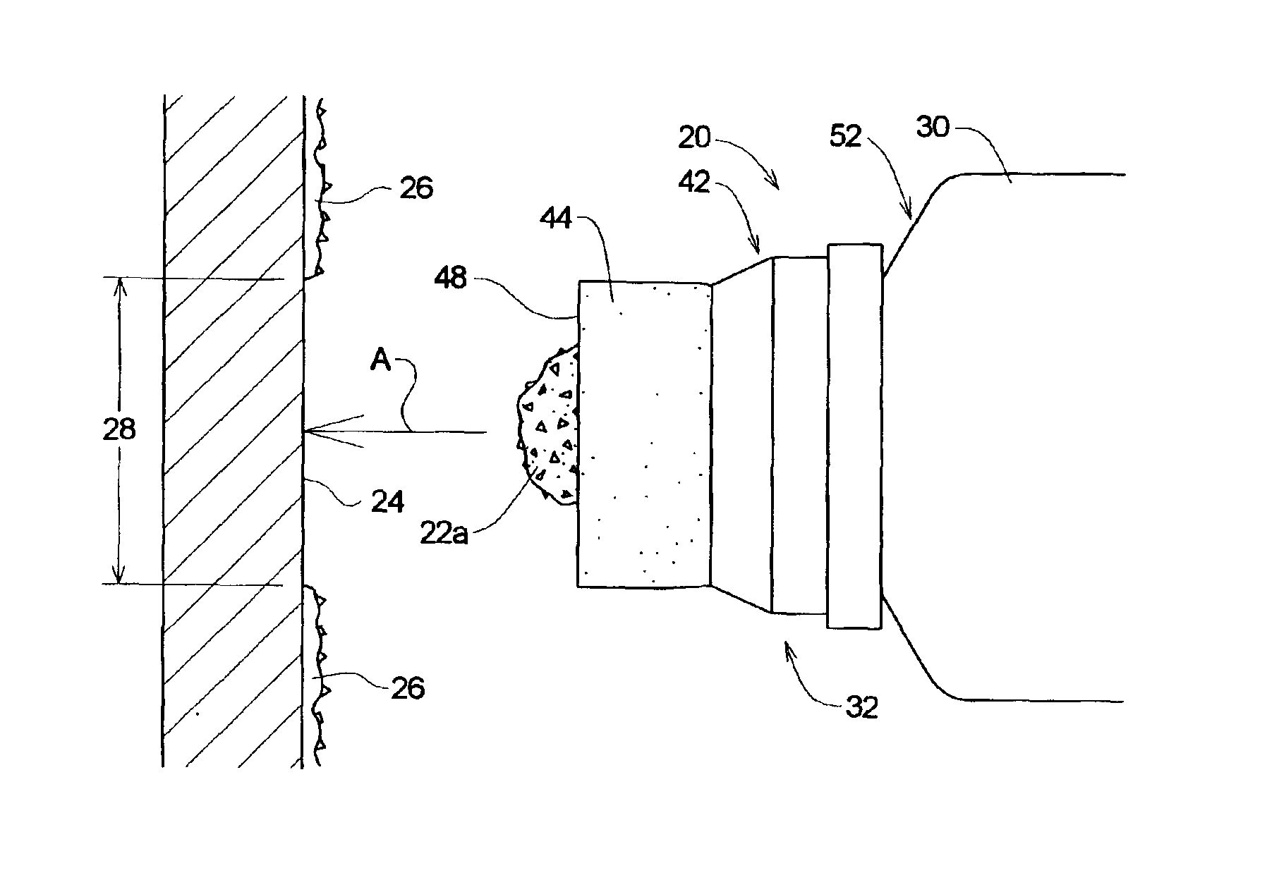
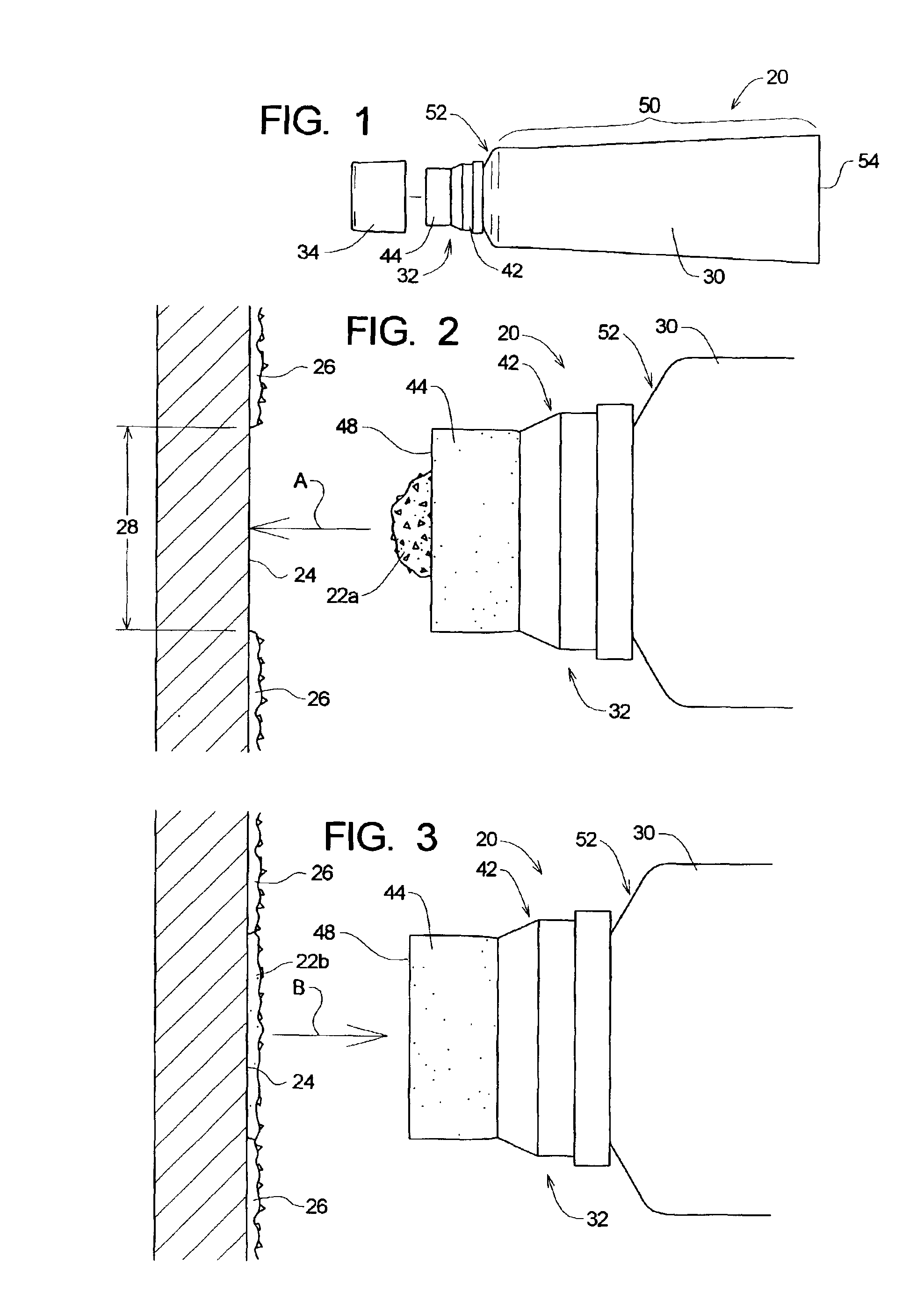
[0016]Referring initially to FIG. 1, depicted therein is a dispensing system 20 constructed in accordance with, and embodying, the principals of the present invention. As shown in FIGS. 2 and 3, the dispensing system 20 is used to apply new texture material 22 to a wall or ceiling surface 24. Existing material 26 is present on the exemplary surface 24, and an area 28 to be patched is shown in FIG. 2. The dispensing system 20 is of particular significance in the context of patching the area 28 of the wall surface 24 to match the existing texture material 26.

[0017]FIG. 2 also shows new texture material, indicated by reference character 22a, in the process of being dispensed from the system 20. FIG. 3 shows, as indicated by reference character 22b, the new texture material 22 applied to the surface 24 over the area 28 to be patched.

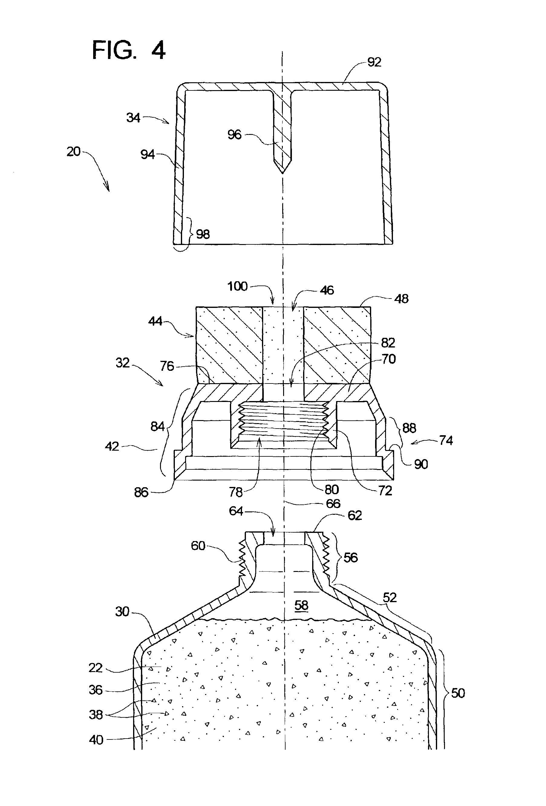
[0018]Texture material typically comprises a base 36, a particulate 38, and a carrier 40. The base 36 typically comprises a binder, a pigment, and filler ma...


PUM


Abstract

A system for patching a destination surface to match an existing texture pattern. The system comprises texture material, a tube member, and a sponge member. The texture material comprises a base, a carrier, and particulate material. The tube member contains the texture material and defines a container opening through which the texture material may flow. The sponge member defines an applicator surface and a sponge opening. The sponge member is secured relative to the tube member, and the texture material is forced out of the tube member through the container opening and the sponge opening and onto the applicator surface. The applicator surface of the sponge member is brought into contact with the destination surface to transfer texture material on the applicator surface to the destination surface.

Description

RELATED APPLICATIONS[0001]This application claims priority of U.S. Provisional Patent Application Ser. No. 60 / 311,424, which was filed on Aug. 10, 2001.TECHNICAL FIELD[0002]The present invention relates to the application of coating materials and, in particular, to the systems and methods for dispensing texture material containing particulate material to a surface such as a ceiling.BACKGROUND OF THE INVENTION[0003]To form interior walls, modern building methods typically employ sheets of drywall material nailed and / or screwed to wall studs. The joints between adjacent sheets of drywall material are covered with fabric tape and drywall mud. The taped and mudded seams are then sanded to obtain a relatively flat surface. The surface is then coated with a primer. The primed surface may be painted to obtain the finished wall surface, or texture material is often applied to the primed drywall surface before painting to create a textured surface pattern underneath the paint layer.[0004]Tex...

Claims


Application Information

Patent Timeline
Patent Type & Authority Patents(United States)
IPC IPC(8): B05C17/00E04F21/02
CPCB05C17/002E04F21/02
Inventor GREER, LESHANSON, RANDY
Owner PPG ARCHITECTURAL FINISHES INC
Features
  • Generate Ideas
  • Intellectual Property
  • Life Sciences
  • Materials
  • Tech Scout
  • Unparalleled Data Quality
  • Higher Quality Content
  • 60% Fewer Hallucinations
Learn More