Drilling guide for dental implantation

a drilling guide and dental implant technology, applied in the field of drilling guides, can solve the problems of requiring a delay of the procedure, requiring a new guide, and not being able to achieve good bone contact, so as to achieve better implant alignment

Inactive Publication Date: 2005-07-05
BLACKLOCK GORDON D
View PDF17 Cites 162 Cited by
  • Summary
  • Abstract
  • Description
  • Claims
  • Application Information

AI Technical Summary

Benefits of technology

[0010]As has been previously stated, the implantation of oral prosthetics requires a drilling into the jaw bone at a relatively precise angle in order to implant an anchor device to which the prosthetic is attached. The present invention presents a drilling guide which enables the dentist or oral surgeon to drill at t

Problems solved by technology

The primary drawback to this method lies in the existing art of the guides, in that only a single channel is provided for directing the drill.
If the angle of that channel is

Method used


Image

  • Drilling guide for dental implantation
  • Drilling guide for dental implantation
  • Drilling guide for dental implantation

Examples


Embodiment Construction

[0031]The drilling guide of the present invention comprises two basic elements, a stent and a guide block, or in alternative embodiments a guide block having integral stent(s), each of which will be set forth individually hereinbelow.

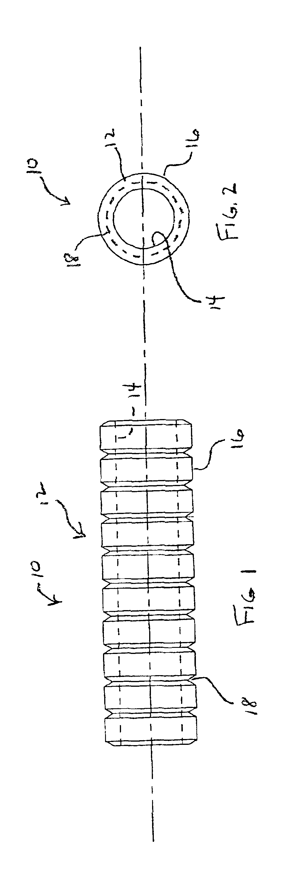
[0032]Referring first to FIGS. 1 and 2, the stent 10 is depicted as being a hollow cylinder 12, having a smooth interior wall 14 and a striated exterior wall 16. The striations 18 are evenly spaced, circumferentially, along the length of cylinder 12, thereby providing a plurality of convenient points for adjusting the length of cylinder 12, and thus establishing a desired length of stent 10.

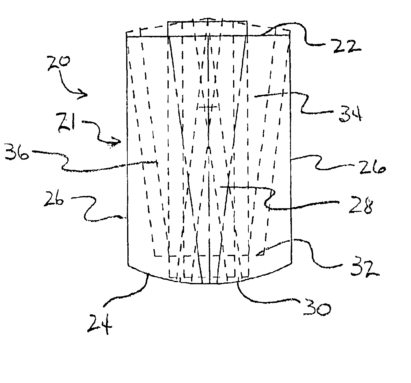
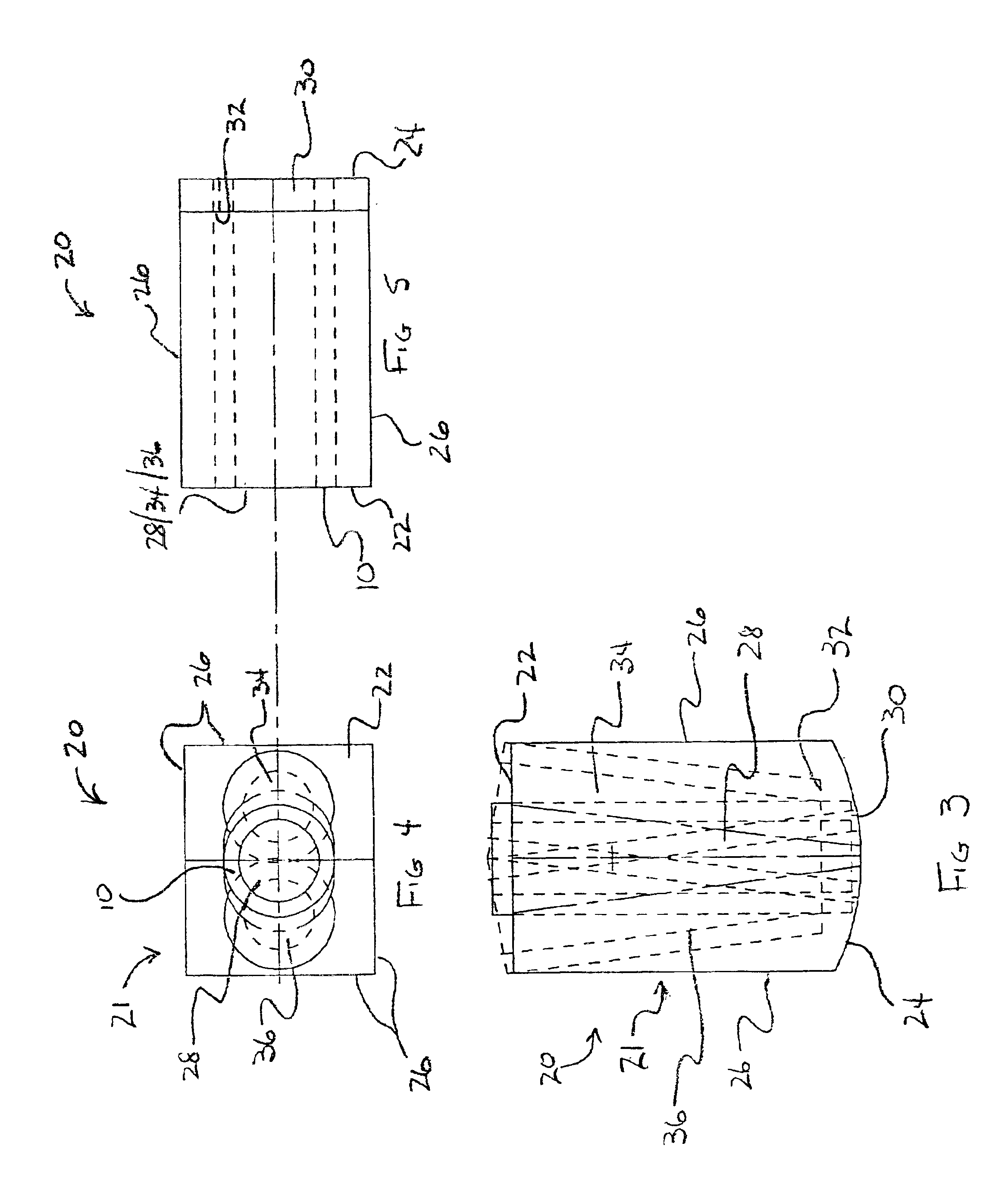
[0033]FIGS. 3 thru 11, collectively, depict three separate embodiments of guide block 20 which may be affixed to an occlusal surface of a jaw, typically by light curable resin or other means. The construction of each embodiment of guide block 20 will first be described, followed by a general description of the method of use for all of the embodiments.

[0034]Referring ...


PUM

PropertyMeasurementUnit
Lengthaaaaaaaaaa
Angleaaaaaaaaaa

Abstract

An adjustable drilling guide, removably mountable to a patient's teeth, having a guide block with at least one stent for guiding a dental drill is disclosed. In a first embodiment, the guide block has a plurality of guide holes disposed at differing angles which may receive a stent for precise drilling at the selected angle. If minor variations need be made, the stent may be moved to a second or third of the guide holes to adjust the angle. In a second embodiment, three distinct stents are formed directly in the guide block allowing for drilling at up to three different angles. A third embodiment has a stent which is pivotable about a pivot point within the guide block, allowing drilling at any angle within the arc of the pivot. The guide block may be fitted to a model of the patient's teeth prior to installation into the mouth to ensure proper fit.

Description

BACKGROUND OF THE INVENTION[0001]1. Field of the Invention[0002]The present invention relates to guides for drilling into a patient's jawbone for insertion of a dental implant. More particularly, the invention comprises a unique guide which allows for minor corrections in the angle and location of entry which are not typically possible with currently available guides.[0003]2. Description of the Prior Art[0004]In dentistry, it is often necessary to implant prosthetic devices, such as artificial teeth. This procedure requires the implantation of an anchor into the jaw, and then the attachment of the prosthetic to the anchor. Typically, the anchor is implanted by drilling into the jaw bone and screwing, or otherwise attaching the anchor into the bone. Proper alignment of the implanted anchor is necessary to ensure that the prosthetic aligns properly with the patient's natural teeth. One method of ensuring proper alignment of the anchor is by making an impression of the patient's mouth ...

Claims


Application Information

Patent Timeline
IPC IPC(8): A61B17/17A61B17/16A61C1/08
CPCA61B17/176A61C1/084Y10T408/567
Inventor BLACKLOCK, GORDON D.
Owner BLACKLOCK GORDON D
Why Eureka
Try Eureka