High speed electrical connector

a high-speed, electrical connector technology, applied in the direction of coupling device connection, connection contact member material, securing/insulating coupling contact member, etc., can solve the problems of signal loss, cross talk increase interference, noise and jitter within the circuit board, connector and system, and reduce the effect of interference, noise and jitter

Inactive Publication Date: 2005-07-05
TYCO ELECTRONICS LOGISTICS AG (CH)
View PDF4 Cites 175 Cited by
  • Summary
  • Abstract
  • Description
  • Claims
  • Application Information

AI Technical Summary

Problems solved by technology

In these high speed data transmission systems, even small impedance fluctuations may pose significant problems, such as signal loss, interference, noise, jitter and the like within each connector.
Cross talk increases the interference, noise, and jitter within the circuit board, connector and system.
Increasing the distance between signal pins of separate differential pairs typically decreases the effects of interference, noise and jitter.
However, electrical and electronic applications today require a large number of differential pairs to be packaged in a small space.

Method used


Image

  • High speed electrical connector
  • High speed electrical connector
  • High speed electrical connector

Examples


Embodiment Construction

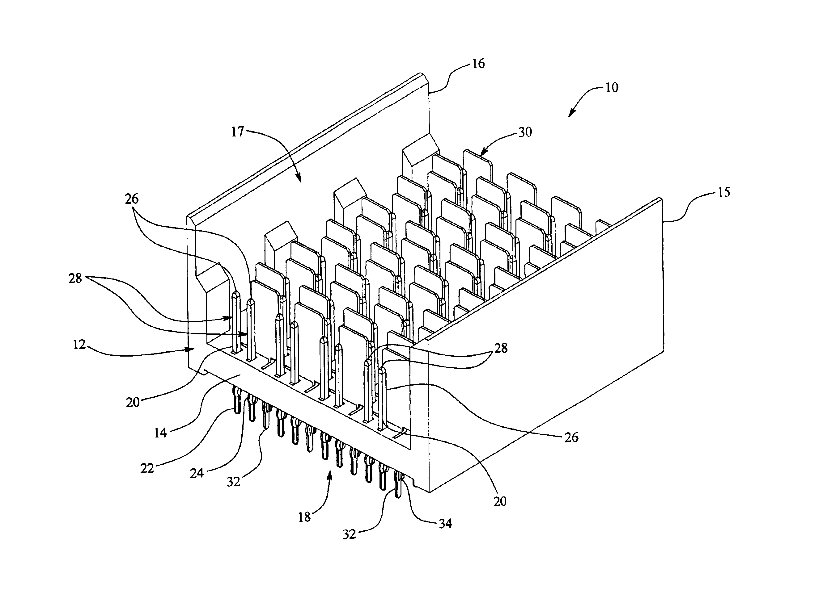
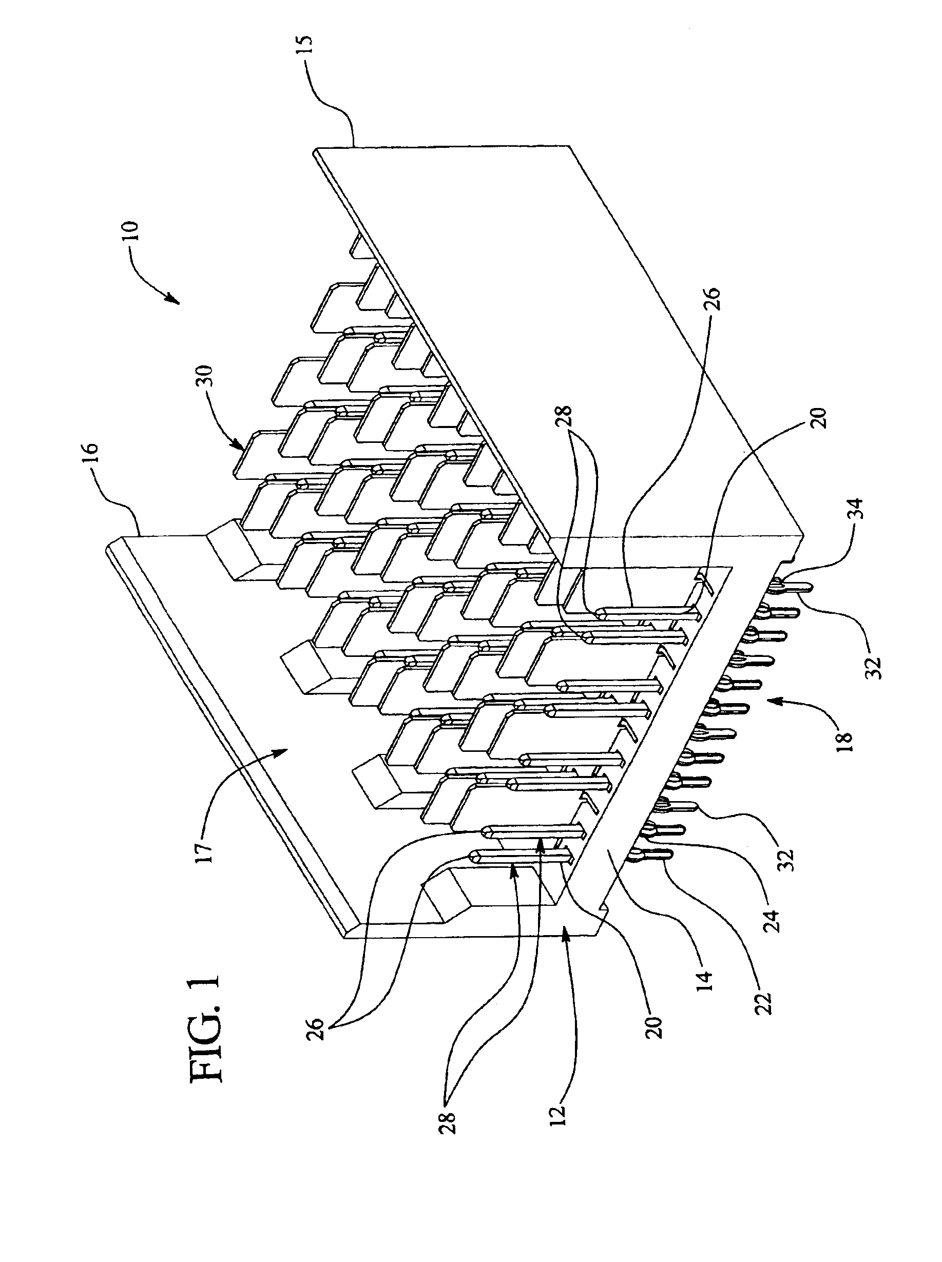
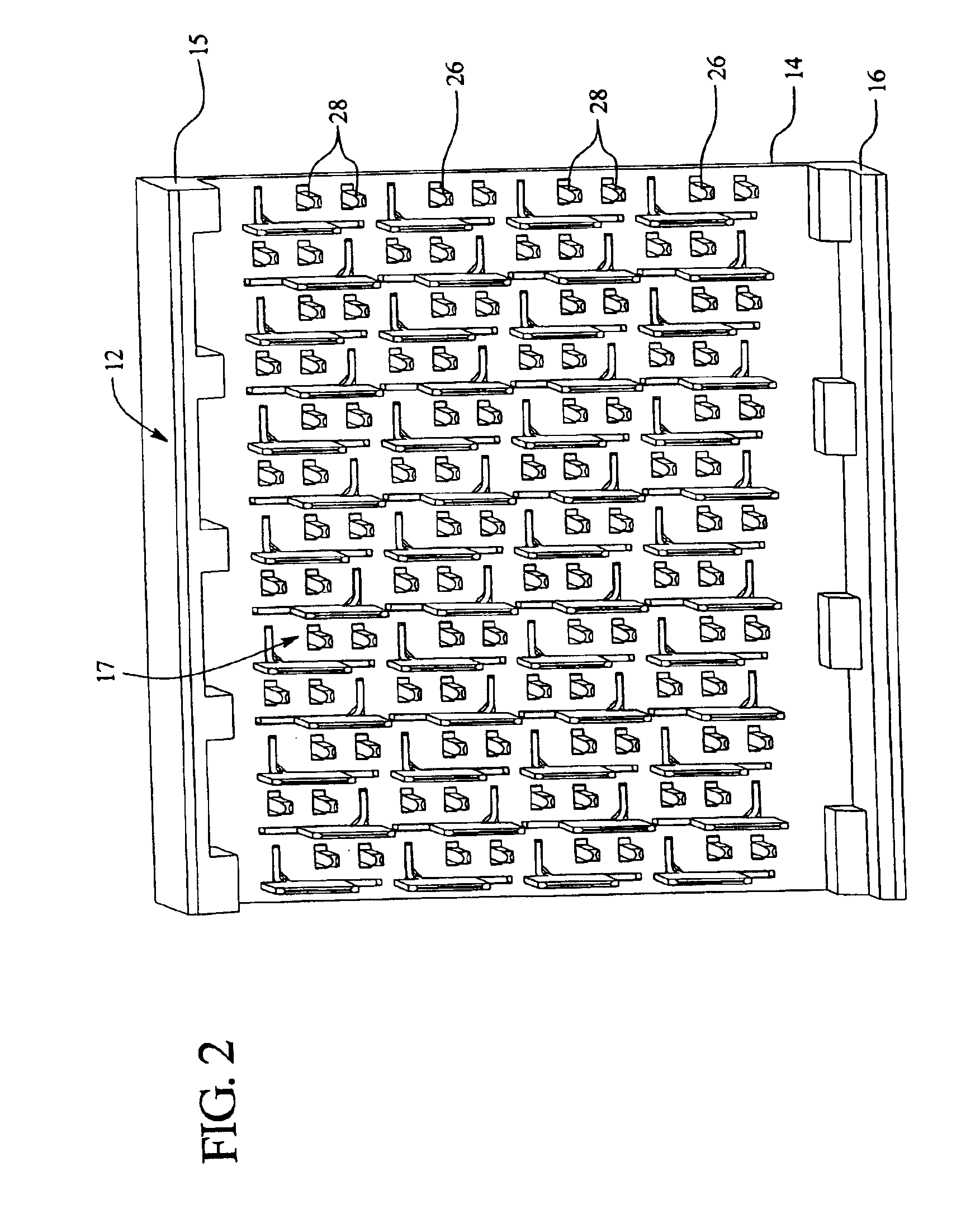
[0032]As shown in FIGS. 1-4, a header connector 10 comprises a dielectric housing 12 including a main wall 14, an upper shroud 15 and a lower shroud 16. The header connector 10 further comprises a plurality of signal contacts 20 and ground contacts 30 that extend through and are secured in the main wall 14. The header connector 10 includes a mating face 17 that interfaces with a mating face 57 of a corresponding receptacle connector 50, shown in FIG. 6. The header connector 10 also includes a board-mounting face 18 that interfaces with a circuit board (not shown) on which the header connector 10 is mounted. The header connector 10 mates with the receptacle connector 50 such that the circuit board on which the header connector 10 mounts is oriented perpendicular to the circuit board, backplane, or other such structure, on which the receptacle connector 50 is mounted or otherwise positioned.

[0033]FIG. 11 illustrates an exemplary signal contact 20, which includes a tail or lead 22 with...


PUM


Abstract

An electrical connector comprising a connector housing holding signal contacts and ground contacts in an array organized into rows. Each row includes pairs of the signal contacts and some of the ground contacts arranged in a pattern, wherein adjacent first and second rows have respective different first and second patterns.

Description

RELATED APPLICATIONS[0001]The present application is a continuation application of U.S. patent application Ser. No. 10 / 255,769, filed on Sep. 25, 2002 now U.S. Pat. No. 6,808,420, which claims priority from U.S. Provisional Patent Application Ser. No. 60 / 382,886, filed on May 22, 2002, which are incorporated by reference herein in their entirety.BACKGROUND OF THE INVENTION[0002]The present invention generally relates to an electrical connector for transmitting high speed electrical signals in differential pair applications.[0003]Many board-to-board connector systems have been proposed for interconnecting circuit boards that include traces arranged to convey differential pairs of signals. The differential pairs include complimentary signals such that if one signal in a differential pair switches from 0 V to 1 V, the other signal in the differential pair switches from 1 V to 0 V. Each connector exhibits a characteristic impedance.[0004]In that past, fluctuations in impedance exhibited...

Claims


Application Information

Patent Timeline
Patent Type & Authority Patents(United States)
IPC IPC(8): H01R13/658H01R12/00H01R12/16H01R12/71
CPCH01R13/65807H01R13/6587Y10S439/943H01R13/6471H01R13/6473
Inventor WHITEMAN, JR., ROBERT NEILDAVIS, WAYNE SAMUEL
Owner TYCO ELECTRONICS LOGISTICS AG (CH)
Why Eureka
Try Eureka