Radar beam steering with remote reflectors/refractors

a technology of reflectors and beams, applied in direction controllers, instruments, antennas, etc., can solve the problems of limited range of ground based radar and ladar systems for detecting, tracking and/or destroying targets, low flying aircraft and cruise missiles, and difficult remote positioning of these systems. , to achieve the effect of increasing the effective range of radar or ladar, there is no suitable device or method available, and no suitable method is availabl

Inactive Publication Date: 2005-07-05
SEC OF THE ARMY
View PDF16 Cites 24 Cited by
  • Summary
  • Abstract
  • Description
  • Claims
  • Application Information

AI Technical Summary

Problems solved by technology

The effective range of ground based radar and ladar systems for detecting, tracking and/or destroying targets, such as low flying aircraft and cruise missiles, is limited by line of sight.
This poses serious concern where it is necessary to detect and engage multiple targets in order to prevent a loss of life at a range that is gre

Method used


Image

  • Radar beam steering with remote reflectors/refractors
  • Radar beam steering with remote reflectors/refractors
  • Radar beam steering with remote reflectors/refractors

Examples


Embodiment Construction

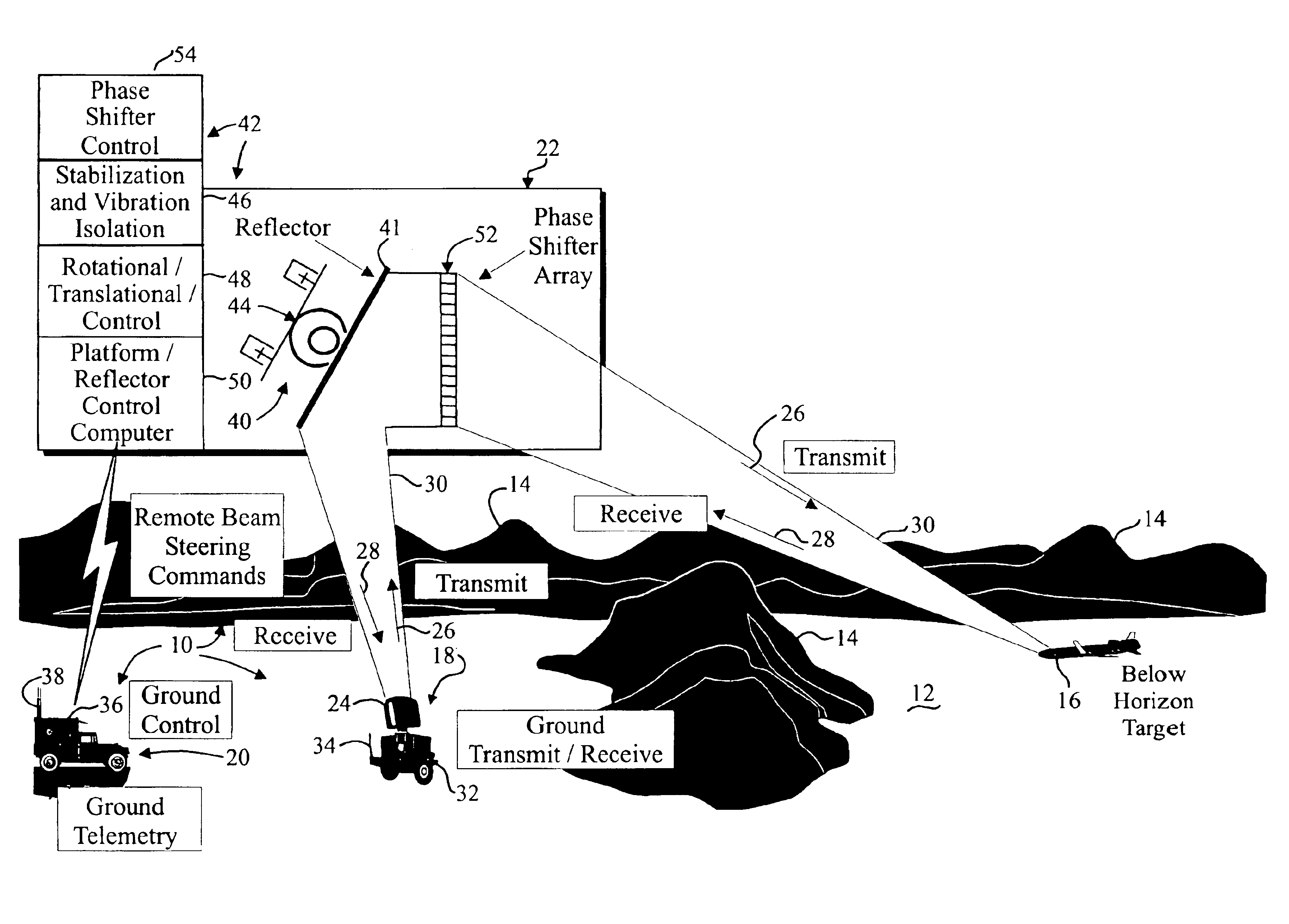
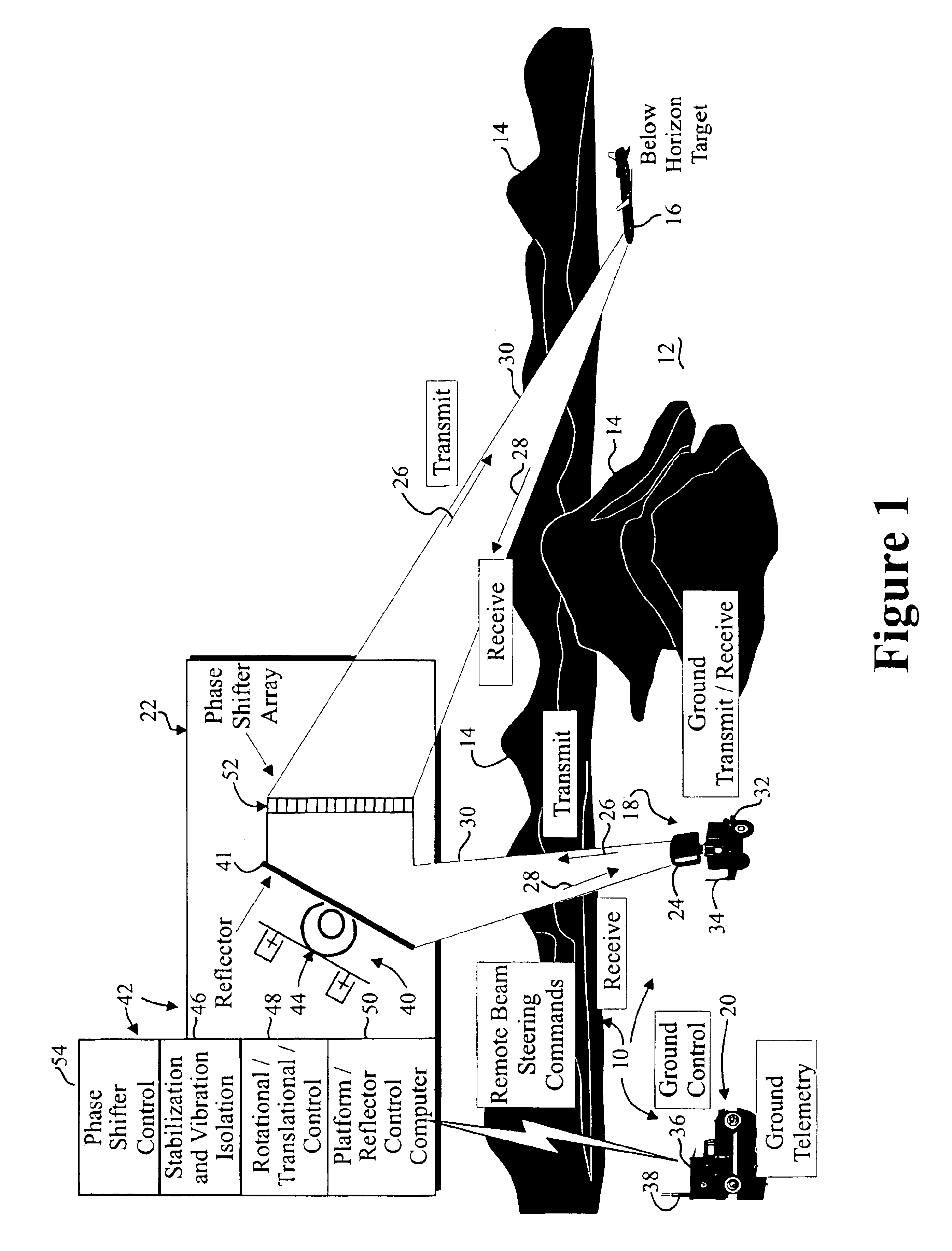
[0010]One embodiment of the present invention concerns locating a reflected energy detecting device such as radar or ladar hardware at ground level and transmitting a radar / ladar beam upward to an elevated platform that comprises a reflector and, optionally, a refractor or phase shifter. Ground control of the elevated reflector and the phase shifter may be made by radar / ladar operators through telemetry links. Translational and rotational position control, along with vertical referencing and stabilization, of the reflector and phase shifter may enable ground based radar operators to view over the horizon with a minimum amount of elevated hardware. Requirements for elevated radar operations are thus greatly reduced over those required in the prior art as ground based radar personnel are able to operate and maintain the radar / ladar hardware. The pointing and positional control for the reflector and the phase shifter may be the only functions that require hardware operation while locat...


PUM


Abstract

A reflected energy detecting device includes a transmitter for transmitting an electromagnetic signal and a receiver for receiving a reflected electromagnetic signal. An antenna may be operatively connected with the transmitter and the receiver for radiating the electromagnetic signal and capturing the reflected electromagnetic signal and the antenna may be movable. A main controller may be provided for controlling operation of the transmitter and the receiver and the movement of the antenna and the reflected energy detecting device may further include at least one platform. The at least one platform may support a remote reflector that is dimensioned and configured to redirect the transmitted electromagnetic signal in a desired direction and a platform controller that is configured to communicate with the main controller and to maintain alignment between the remote reflector and the antenna.

Description

BACKGROUND OF THE INVENTION[0001]1. Field of the Invention[0002]The present invention relates to devices and methods for detecting reflected energy and, more particularly, to radar and ladar systems with enhanced range.[0003]2. Related Art[0004]The effective range of ground based radar and ladar systems for detecting, tracking and / or destroying targets, such as low flying aircraft and cruise missiles, is limited by line of sight. The line of sight in various directions from any particular location may be defined by the curvature of the earth and / or terrain features such as valleys, mountains and hills. This poses serious concern where it is necessary to detect and engage multiple targets in order to prevent a loss of life at a range that is greater than the effective range of the radar or ladar system.[0005]In an attempt to increase the effective range, radar and ladar systems have been remotely located on towers, in aerostats, airships and aircraft. This requires that hundreds of p...

Claims


Application Information

Patent Timeline
IPC IPC(8): G01S7/02G01S7/28G01S13/00G01S13/02H01Q19/10
CPCG01S7/02G01S7/2813H01Q19/104G01S13/0218
Inventor RILEY, LEON H.STRICKLAND, BRIAN R.
Owner SEC OF THE ARMY
Why Eureka
Try Eureka