Method for determining whether two rectangles of an electronic circuit structure overlap

Active Publication Date: 2005-07-05
AVAGO TECH INT SALES PTE LTD
View PDF2 Cites 0 Cited by
  • Summary
  • Abstract
  • Description
  • Claims
  • Application Information

AI Technical Summary

Benefits of technology

[0005]Embodiments of the invention, to be discussed in detail below, may be described as methods of modifying two rectangles of an electronic circuit structure in such a way as to reduce the amount of computation necessary to determine if the two rectangles overlap. In one embodiment, a first rectangle is reduced in both x- and y-directions to a single point residing in the center of

Problems solved by technology

Such a condition often results in two separate circuits of the IC being inadvertently connected together, thus causing improper operation of the IC.
As a result, the amount of time required for each single operation of checking for overlap between two rectangles can significantly influence the overall time required to perform such a check on an entire IC design database.
Such iterations are necessarily time-consuming, causing an inordinate amount of computer processing t

Method used


Image

  • Method for determining whether two rectangles of an electronic circuit structure overlap
  • Method for determining whether two rectangles of an electronic circuit structure overlap
  • Method for determining whether two rectangles of an electronic circuit structure overlap

Examples


second embodiment

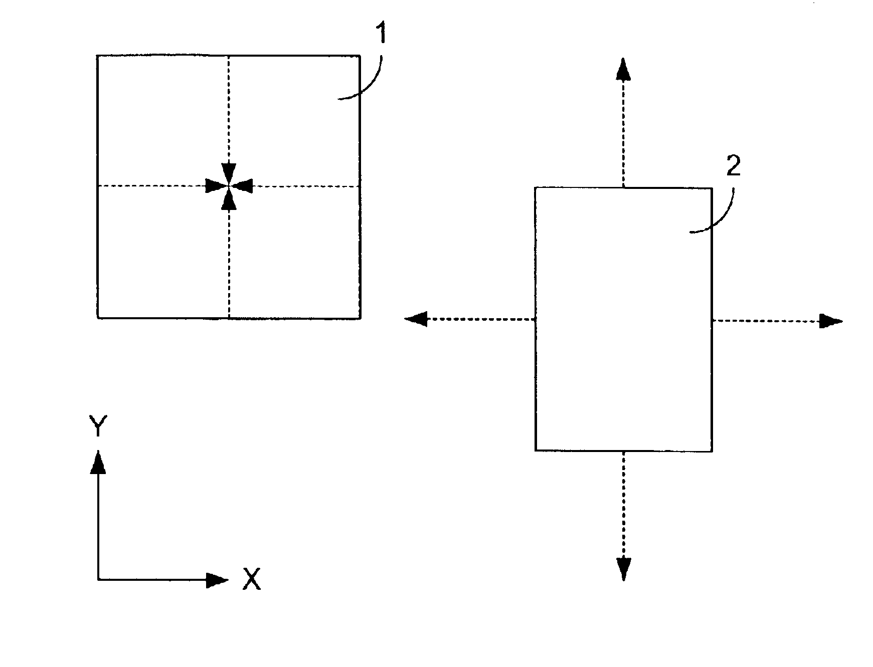
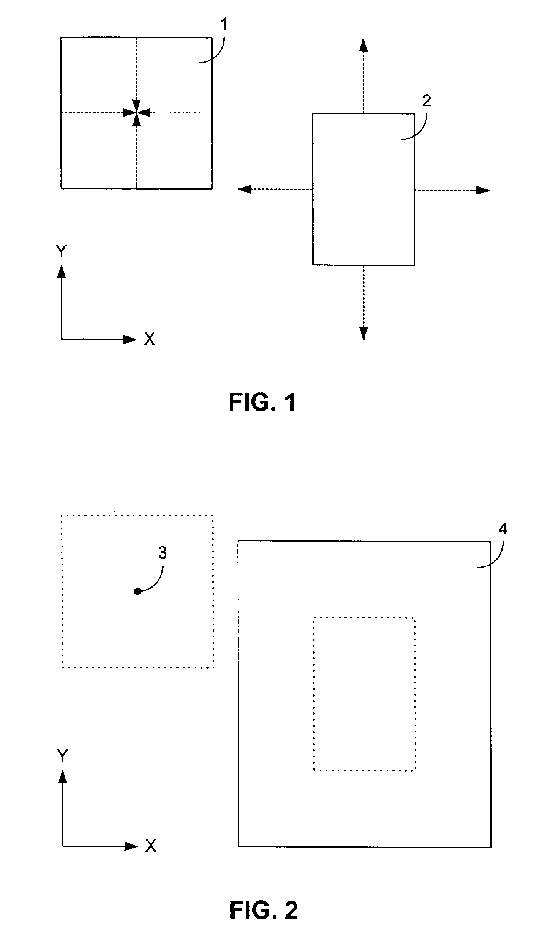
[0018]One embodiment of the invention is shown conceptually in FIG. 1 through FIG. 4, while a second embodiment is displayed in a similar fashion in FIG. 6 through FIG. 9. In each of the figures, the sides of the rectangles are aligned parallel and perpendicular to an x-y coordinate system, as indicated by the x- and y-axes denoted in each of the figures.

first embodiment

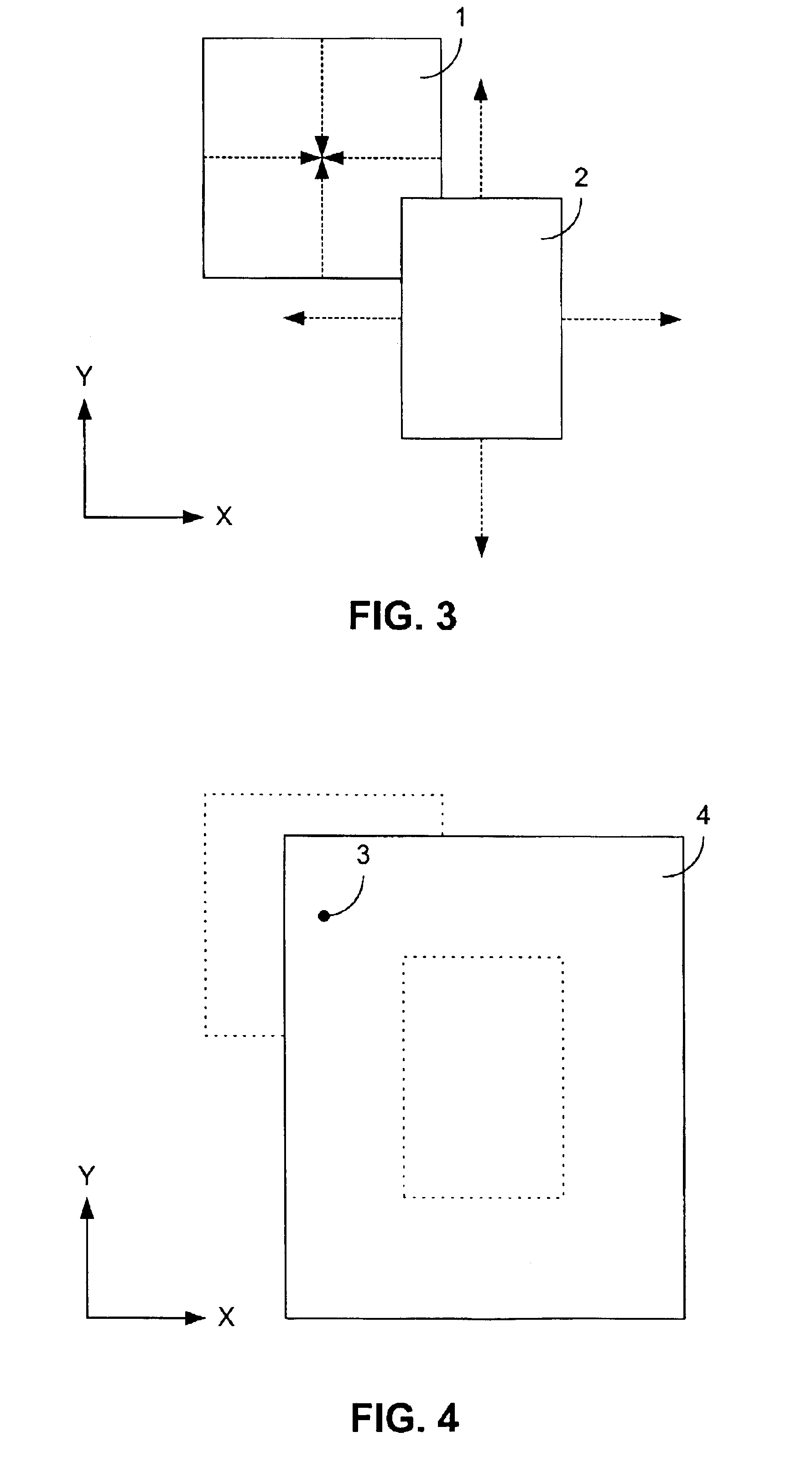
[0019]Relating to the first embodiment, in FIG. 1 and FIG. 2 a first rectangle 1 and a second rectangle 2 do not overlap. To determine whether the first rectangle 1 and the second rectangle 2 overlap, the first rectangle 1 is reduced along both the x-direction and y-direction, as shown in FIG. 1, from a rectangle to a single point 3, as indicated in FIG. 2. The single point 3 is positioned in the center of the first rectangle 1. This positioning is accomplished by moving opposing sides of the rectangle equal distances toward each other along both the x-axis and the y-axis.

[0020]Similarly, the second rectangle 2 is expanded in both the x-direction and y-direction by moving opposing sides of the rectangle outward from the center of the second rectangle 2. Each side of the second rectangle 2 is moved by a distance equal to that which the corresponding sides of the first rectangle 1 were moved in the opposite direction. For example, if each of the two vertical sides of the first rectang...


PUM


Abstract

A method of comparing two rectangles of a circuit design structure for overlap is provided. The two rectangles being compared are modified conceptually in such a way as to reduce the amount of computation necessary to determine if the two rectangles overlap. In one embodiment, a first rectangle is reduced in both x- and y-directions to a single point residing in the center of that rectangle, while the size of the second rectangle is expanded in both x- and y-directions by the same amount, resulting in an enlarged rectangle. A determination of whether the single point resides within the enlarged rectangle thus indicates if the two original rectangles overlap. Similarly, in another embodiment, a first rectangle is reduced in the x-direction only, resulting in a y-directed line segment, while a second rectangle is reduced in the y-direction, resulting in an x-directed line segment. The y-directed line segment is extended by the amount that the second rectangle was reduced in the y-direction, and the x-directed line segment is extended by the amount that the first rectangle was reduced in the x-direction. A determination of whether the x-directed line segment and the y-directed line segment intersect indicates if the first and second rectangles overlap.

Description

BACKGROUND OF THE INVENTION[0001]As a part of the normal integrated circuit (IC) design process, a consistency check of the physical layout of each layer of the IC, including metal layers, semiconductor layers, and the like, is normally performed on the IC design database to detect and correct any mistakes in the design. One of the checks typically performed on such a database is ensuring two adjacent rectangular portions of a layer, such as two metal connections of an IC metal layer, do not overlap. Such a condition often results in two separate circuits of the IC being inadvertently connected together, thus causing improper operation of the IC. Such database checks ordinarily must be performed many thousands of times for each IC due to the large number of transistors and other circuit components normally found in today's integrated circuit technologies. As a result, the amount of time required for each single operation of checking for overlap between two rectangles can significant...

Claims


Application Information

Patent Timeline
IPC IPC(8): G09G5/00G06F17/50
CPCG06F17/5081G06F30/398
Inventor HASKIN, BRYAN
Owner AVAGO TECH INT SALES PTE LTD
Why Eureka
Try Eureka