Disk drive employing BEMF spindle speed control or wedge spindle speed control

Inactive Publication Date: 2005-07-05
WESTERN DIGITAL TECH INC
View PDF5 Cites 115 Cited by
  • Summary
  • Abstract
  • Description
  • Claims
  • Application Information

AI Technical Summary

Benefits of technology

[0013]In yet another embodiment, the time-out error condition subsides after successfully accumulating a predetermined number of wedge time counter values and updating the spindle control current.
[0014]In still another embodiment, if the time-out error condition does not subside within a predetermined failure interval, the spindle motor is controlled in response to the BEMF speed error generated from the BEMF signal. In one embodiment, the failure interval equals one revolution of the disk. In one embodiment, if the disk controller successfully accumulates a predetermined number of wedge time counter values and updates the spindle control current, the disk controller begins controlling the spindle motor in response to the wedge speed error.
[0015]In still another embodiment, the disk drive further comprises a current modulator for generating a PWM signal representing the spindle control current. BEMF detection window circuitry periodically disables the PWM signal for a predetermined interval to attenuate noise in the BEMIF voltage while the BEMF detector compares the BEMF voltage to the threshold. The disk controller disables the BEMF detection window circuitry while updating the spindle control current in response to the wedge speed error.
[0016]In yet another embodiment, the disk controller switches from the wedge spindle speed control mode to the BEMF spindle speed control mode. During a settle interval between modes, an at-speed current is applied to the sp

Problems solved by technology

However, the bandwidth of a spindle speed control loop using BEMF voltage as feedback may be insufficient for a desired recording density or vibration tolerance.
However, the '202 patent discloses very little implemen

Method used


Image

  • Disk drive employing BEMF spindle speed control or wedge spindle speed control
  • Disk drive employing BEMF spindle speed control or wedge spindle speed control
  • Disk drive employing BEMF spindle speed control or wedge spindle speed control

Examples


Embodiment Construction

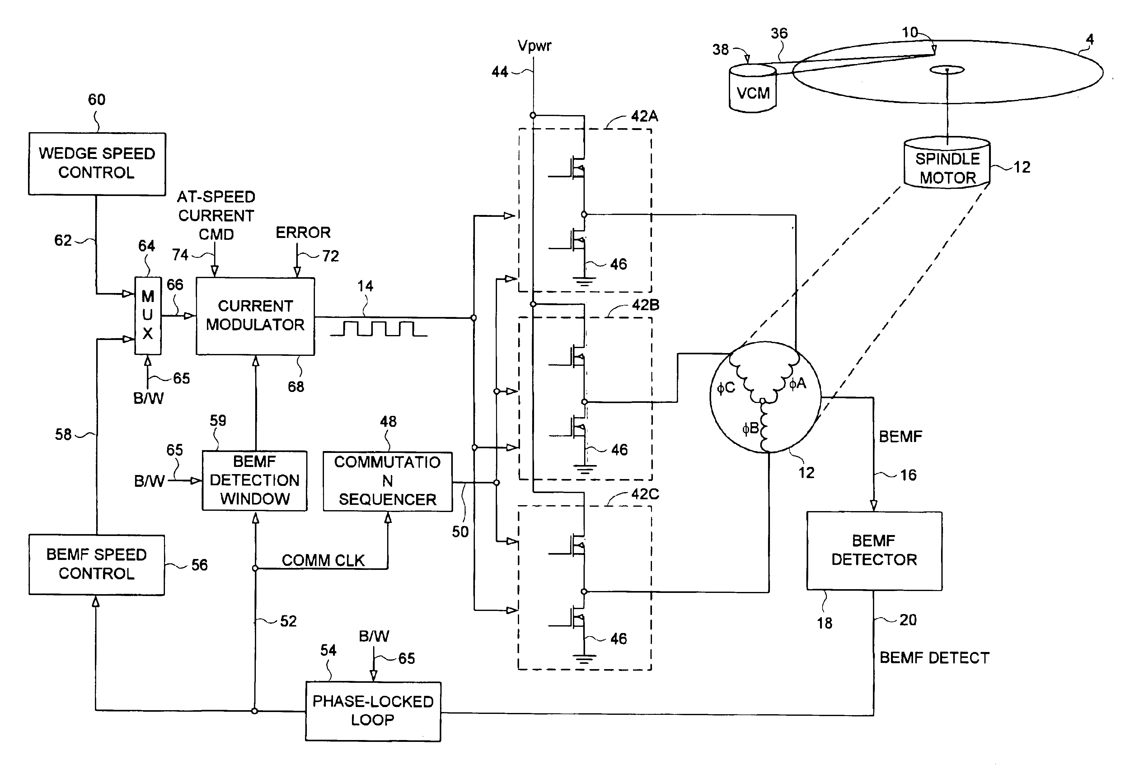
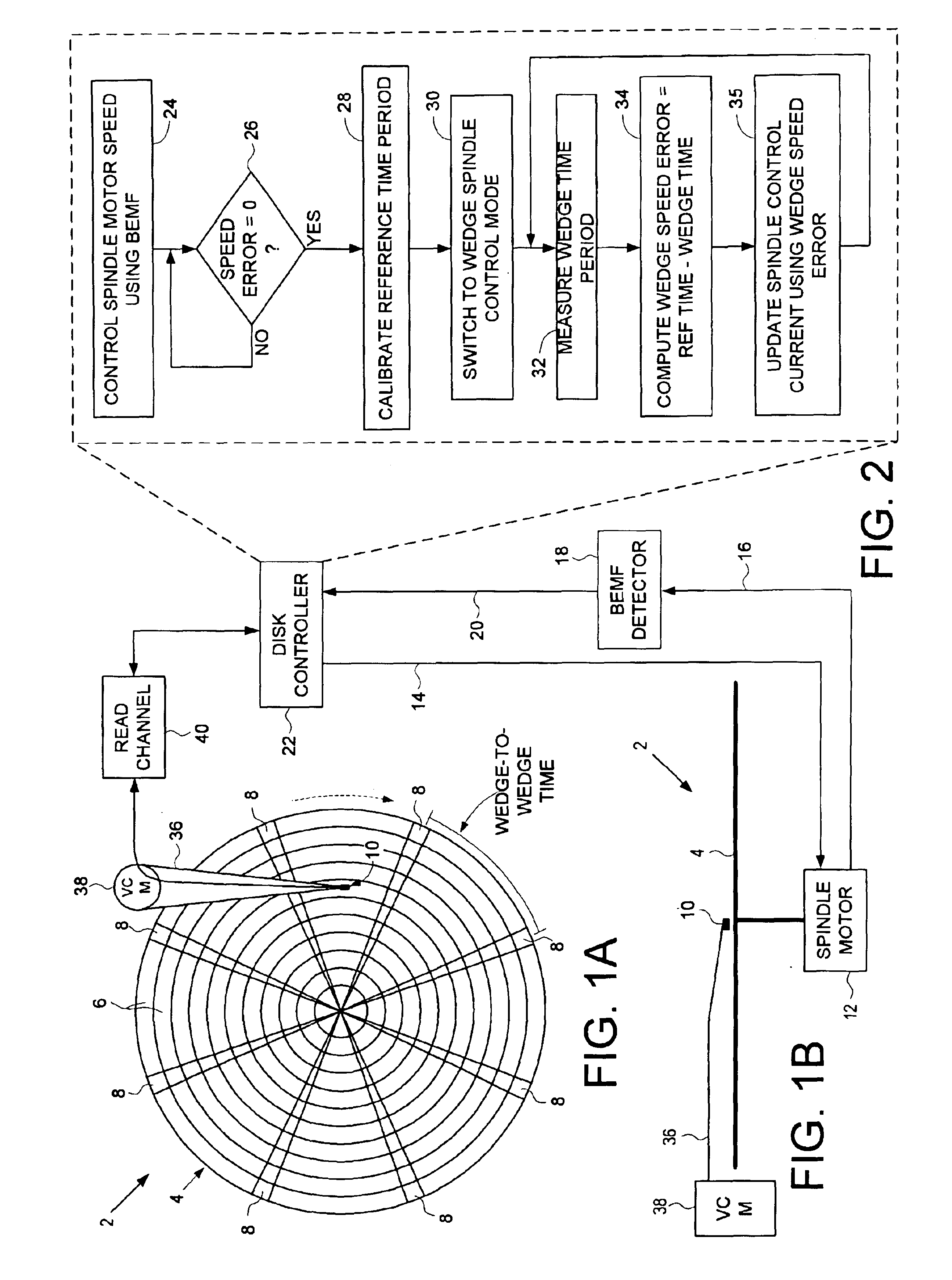
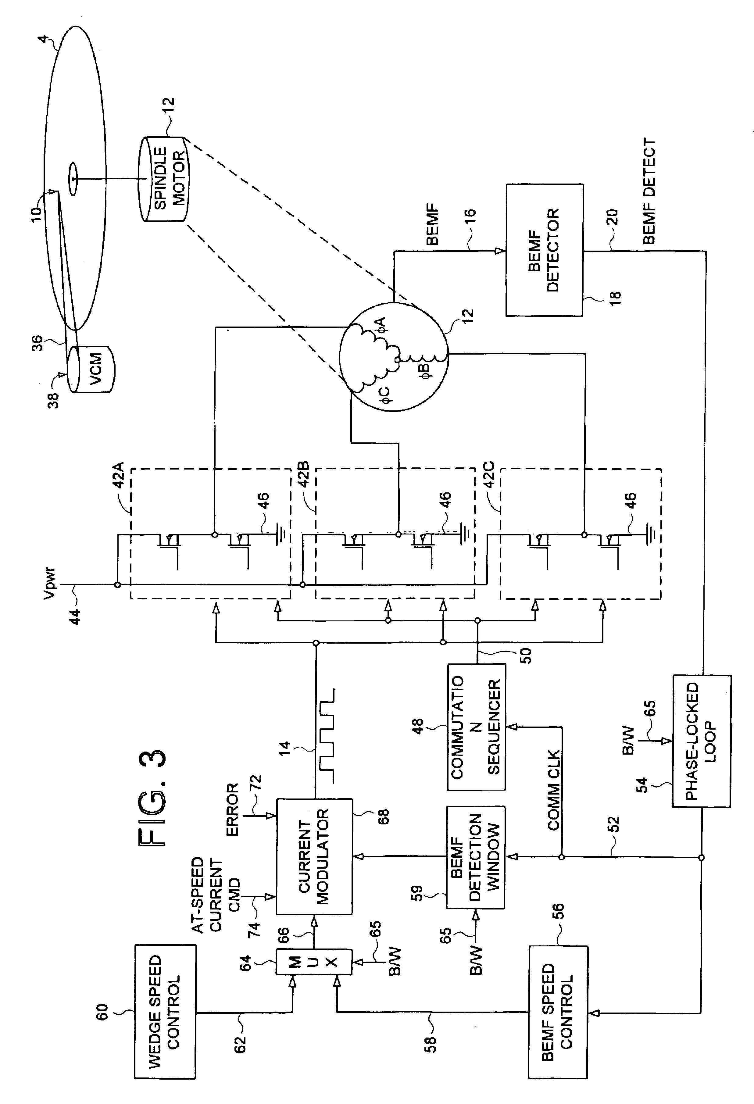
[0024]FIGS. 1A and 1B show a disk drive 2 according to an embodiment of the present invention comprising a disk 4 having a plurality of tracks 6, wherein each track 6 comprises a plurality of data sectors and a plurality of servo wedges 8. A head 10 is actuated over the disk 4, and a spindle motor 12 rotates the disk 4 at an operating speed in response to a spindle control current 14, the spindle motor 12 comprising a plurality of windings which generate a back electromotive force (BEMF) voltage 16. A BEMF detector 18 generates a BEMF signal 20 by comparing the BEMF voltage 16 to a threshold. A disk controller 22 executes the steps of the flow diagram shown in FIG. 2 to control the spindle motor 12 by generating the spindle control current 14 during a BEMF spindle speed control mode or a wedge spindle speed control mode. At step 24, a BEMF speed error is generated in response to the BEMF signal 20 during the BEMF spindle speed control mode, and the spindle control current 14 is upda...


PUM


Abstract

A disk drive is disclosed employing either back electromotive force (BEMF) spindle speed control or wedge spindle speed control. The BEMF spindle speed control is used to calibrate a reference time period representing an accumulation of a predetermined number of wedge-to-wedge times. During wedge spindle speed control, a wedge time period representing an accumulation of a predetermined number of wedge-to-wedge times is measured, and a wedge speed error is computed as the difference between the reference time period and the wedge time period.

Description

BACKGROUND OF THE INVENTION[0001]1. Field of the Invention[0002]The present invention relates to disk drives. In particular, the present invention relates to a disk drive employing back electromotive force (BEMF) spindle speed control or wedge spindle speed control.[0003]2. Description of the Prior Art[0004]A disk drive typically comprises one or more disks rotated by a spindle motor while heads are actuated radially over the disk surfaces. Each disk surface comprises a number of radially spaced, concentric tracks, where each track is divided into a number of data sectors. A number of embedded servo wedges are also written on each disk surface which facilitate seeking the head and maintaining the head over the centerline of a target track during read and write operations. The disks are rotated at a constant angular velocity (CAV) while varying the data rate from an inner diameter zone to an outer diameter zone to maximize the recording density.[0005]In order to achieve accurate repr...

Claims


Application Information

Patent Timeline
IPC IPC(8): G11B15/46G11B5/55
CPCG11B5/5569G11B5/5534
Inventor TU, KUANG-YANGJI, CHUANWEN
Owner WESTERN DIGITAL TECH INC
Why Eureka
Try Eureka