Method for assembling a package for sutures

a technology of sutures and packaging, applied in the field of packaging methods, can solve the problems of limited size of dispenser cartons, and achieve the effects of low manufacturing cost, fast application, and not slowing down

Inactive Publication Date: 2005-07-12
ETHICON INC
View PDF14 Cites 327 Cited by
  • Summary
  • Abstract
  • Description
  • Claims
  • Application Information

AI Technical Summary

Benefits of technology

[0009]Another object of the present invention is to provide an attachment method for suture package moldings that is fast to apply, thereby not slowing down, for example, a connected molding machine or other piece of process equipment.
[0010]Yet another object of the present invention is to provide a novel low manufacturing cost process, not requiring added parts or materials such as fasteners.
[0011]Still yet another object of the present invention is to provide a novel process that minimizes the thickness of a suture tray package and that it provides a secure bond at critical locations on the package.

Problems solved by technology

A dispenser carton is typically limited in size by a conventional hospital operating room storage rack system.

Method used


Image

  • Method for assembling a package for sutures
  • Method for assembling a package for sutures
  • Method for assembling a package for sutures

Examples


Embodiment Construction

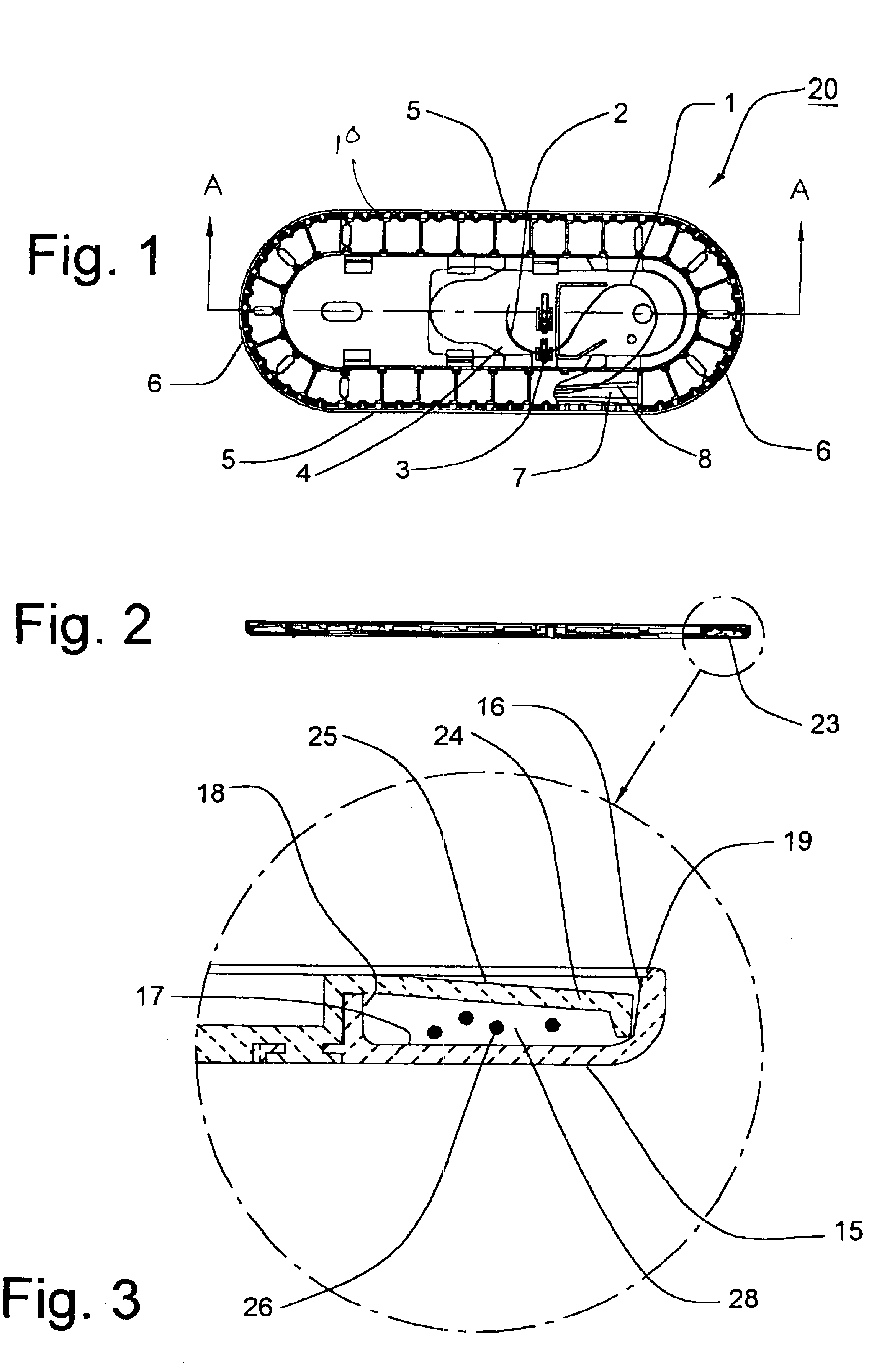
[0038]FIG. 1 illustrates a plan view of a molded plastic suture package 20, further illustrating a suture 1 and attached needle 2 mounted therein. The needle 2 is secured in a needle park 3 molded into the floor 4 of the package 20. The outer periphery 10 of package 20 is seen to have substantially straight parallel sides 5 connected by opposed semicircular ends 6. Inboard of the outer periphery and parallel thereto is an internal, enclosed suture channel 7 containing the coiled suture loops 8.

[0039]Referring to FIG. 2, which is an elevation view of section A—A taken through FIG. 1, and FIG. 3, an enlarged view of the suture channel end portion 23 of FIG. 2 is illustrated.

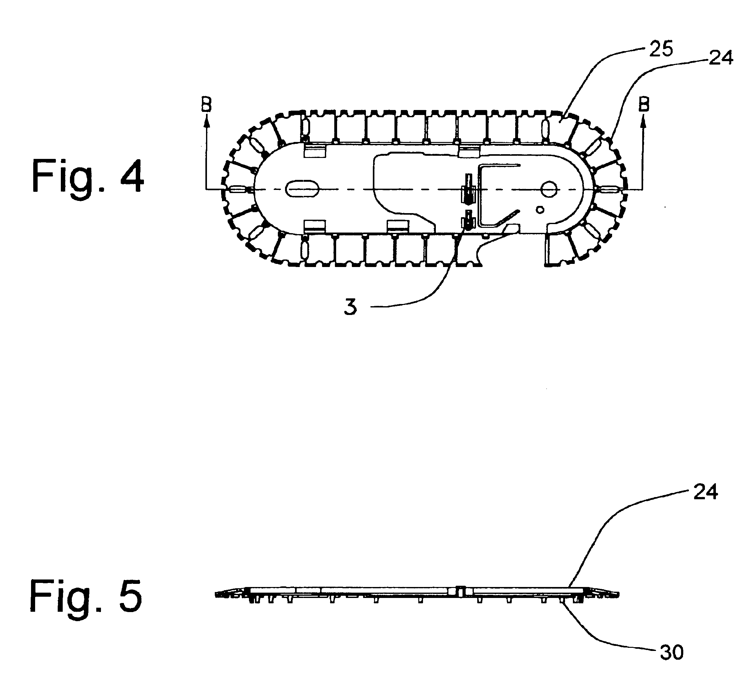
[0040]The package 20 is seen to have an injection molded top and bottom members 24 and 15, respectively. Said bottom member 15 has a suture channel vertical outer wall 16, floor 17, vertical inner wall 18, and a peripheral recessed groove 19 for a label panel (not shown).

[0041]The top member 24 is seen to have a pl...


PUM

PropertyMeasurementUnit
ultrasonic energyaaaaaaaaaa
forceaaaaaaaaaa
shapeaaaaaaaaaa

Abstract

A novel method and apparatus for riveting a two-piece suture tray package. A two-piece suture tray assembly is provided having a top member and a bottom member. The top member has a top and a bottom, and plurality of rivet members extending down from the bottom of the top member. The rivet members have free ends. The bottom member has a top and a flat bottom surface, and a plurality of rivet receiving openings extending therethrough. A counterbore surrounds each rivet receiving opening in the flat bottom surface. An ultrasonic riveting apparatus is provided having a clamp member with a cavity, and an ultrasonic horn member having a flat bottom moveably mounted in the cavity. The assembly is mounted in the riveting apparatus and engaged by the clamp member. The flat bottom of the horn member engages the free ends of the rivet members, and when energized by an ultrasonic generator, causes the free ends of the rivet members to deform into the counterbores, such that the free ends are flat and in alignment with the bottom surface of the bottom member.

Description

TECHNICAL FIELD[0001]The field of art to which this patent application relates is methods for assembling packages, in particular, method of assembling packages for sutures.BACKGROUND OF THE INVENTION[0002]Packages for surgical sutures are well known in the art. The function of the package is to contain and protect the suture strand material, and any attached surgical needles, and to provide low-force, tangle-free dispensing when used by the health care professional in a surgical procedure. One type of package that is known in this art is a tray package having a suture channel. Suture is loaded into the package by winding the suture into a suture channel, typically having an oval configuration. Suture tray packages are disclosed in U.S. Pat. Nos. 6,047,815 and 6,135,272, which are incorporated by reference. It is preferable that the package dispense the suture strand in a form that is relatively straight, retaining a minimal amount of ‘memory’, of the coiled shape of the suture packa...

Claims


Application Information

Patent Timeline
Patent Type & Authority Patents(United States)
IPC IPC(8): A61B17/06B65B51/22A61B17/00
CPCA61B17/06133B29C65/08B29C65/606B29C65/7841B29C66/54B29C66/80B29C66/8322B65B51/22A61B2017/00526A61B2017/06142B29C66/73921B29C66/8246B29C66/71B29C66/8242B29C66/1122B29K2023/065B29K2023/12B29K2025/06B29K2069/00
Inventor DEY, CLIFFORD A.CERWIN, ROBERT J.WARNER, THOMAS
Owner ETHICON INC
Why Eureka
Try Eureka