Vehicle air conditioner with automatic control of main blower and sub-blower

a technology of air conditioner and sub-blower, which is applied in the direction of heating types, domestic cooling devices, and vehicle parts, etc., can solve the problems of inability to adjust the temperature of air blown to the rear upper side, the air amount blown to the rear lower side becomes smaller, and the effect of improving the air conditioning fee given to the passenger on the rear seat in the passenger compartmen

Inactive Publication Date: 2005-07-12
DENSO CORP
View PDF5 Cites 10 Cited by
  • Summary
  • Abstract
  • Description
  • Claims
  • Application Information

AI Technical Summary

Benefits of technology

[0012]In view of the above-described problems, it is an object of the present invention to provide a vehicle air conditioner having a main blower for blowing air toward a first area of a passenger compartment and a sub-blower for blowing a part of air blown by the main blower toward a second area in the passenger compartment. In the vehicle air conditioner, an air amount to be blown to the second area in the passenger compartment can be accurately automatically controlled.
[0013]According to the present invention, a vehicle air conditioner includes a main blower for blowing air, a heat exchange unit for performing heat exchange with air blown by the main blower, and a case having a first air passage through which conditioned air after being heat-exchanged with the heat exchange unit flows toward a first area in the passenger compartment and a second air passage through which conditioned air after being heat-exchanged in the heat exchange unit flows toward a second area in the passenger compartment. In the air conditioner, a sub-blower for blowing conditioned air in the second air passage toward the second area of the passenger compartment is disposed in the second air passage having an air flow resistance larger than that in the first air passage, and a control unit for controlling operation of the main blower and the sub-blower includes a first control means for controlling an air amount blown by the main blower and a second control means for controlling an air amount blown by the sub-blower. In addition, the second control means changes the air amount blown by the sub-blower in accordance with a change of the air amount blown by the main blower. For example, the second control means increases the air amount blown by the sub-blower in accordance with a decrease of the air amount blown by the sub-blower. Accordingly, even when the air amount of the main blower changes, the air amount blown by the sub-blower can be automatically corrected. Therefore, the air amount blown by the sub-blower can be maintained approximately at a predetermined target value. As a result, the air conditioning of the second area in the passenger compartment can be accurately performed without being affected by a change of the air amount of the sub-blower.
[0015]For example, the first area is a front seat area in the passenger compartment, the first air passage is a front air passage through which air flows toward the front seat area, the second area is a rear seat area in the passenger compartment, and the second air passage is a rear air passage through which air flows toward the rear seat area. In this case, preferably, the rear air passage includes a rear face passage through which air flows toward a rear upper side and a rear foot passage through which air flows toward a rear lower side, and a rear mode selecting unit is disposed for opening and closing the rear face opening and the rear foot opening. Therefore, by the operation of the sub-blower, air conditioning feeing given to a passenger on a rear seat in the passenger compartment can be improved.

Problems solved by technology

Further, because cold air immediately after the evaporator of the front air conditioning unit is blown to the rear upper side of the passenger compartment through the rear face duct, the temperature of air blown to the rear upper side cannot be adjusted.
As a result, an air amount to be blown to the rear lower side becomes smaller, and a heating shortage may be caused in the rear seat area of the passenger compartment.
However, there is the same problem also in a case where a front area and a passenger's seat in the passenger compartment are air-conditioned by using the single front air conditioning unit, because air flow resistance in a seat-side air passage becomes extremely large as compared with the air flow resistance in the front air passage.

Method used


Image

  • Vehicle air conditioner with automatic control of main blower and sub-blower
  • Vehicle air conditioner with automatic control of main blower and sub-blower
  • Vehicle air conditioner with automatic control of main blower and sub-blower

Examples


Embodiment Construction

[0023]A preferred embodiment of the present invention will be described with reference to the accompanying drawings.

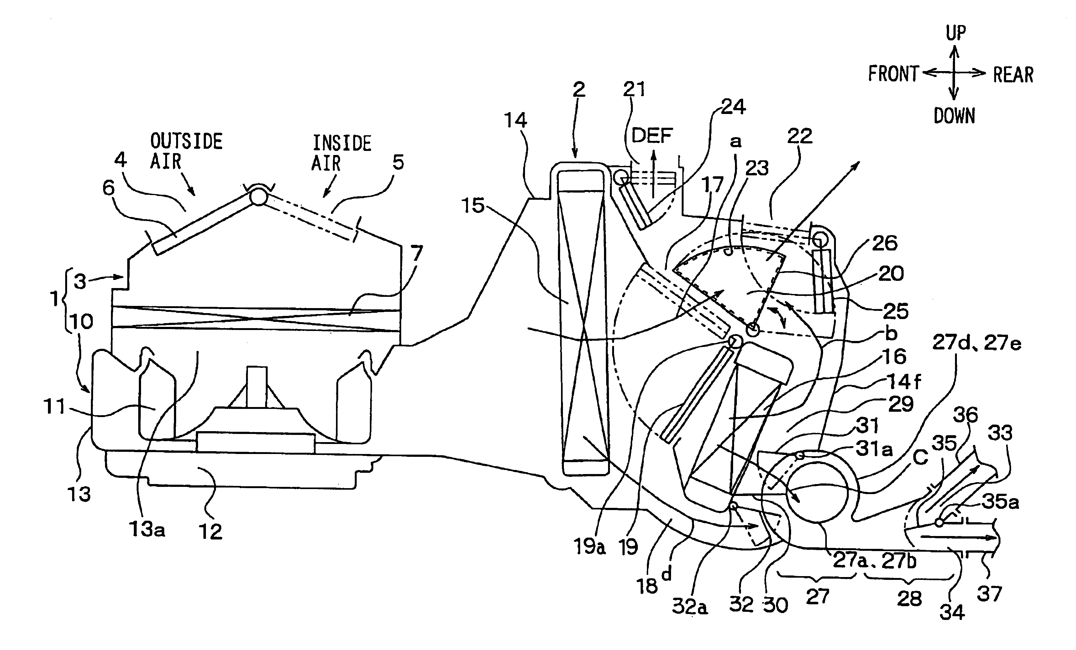
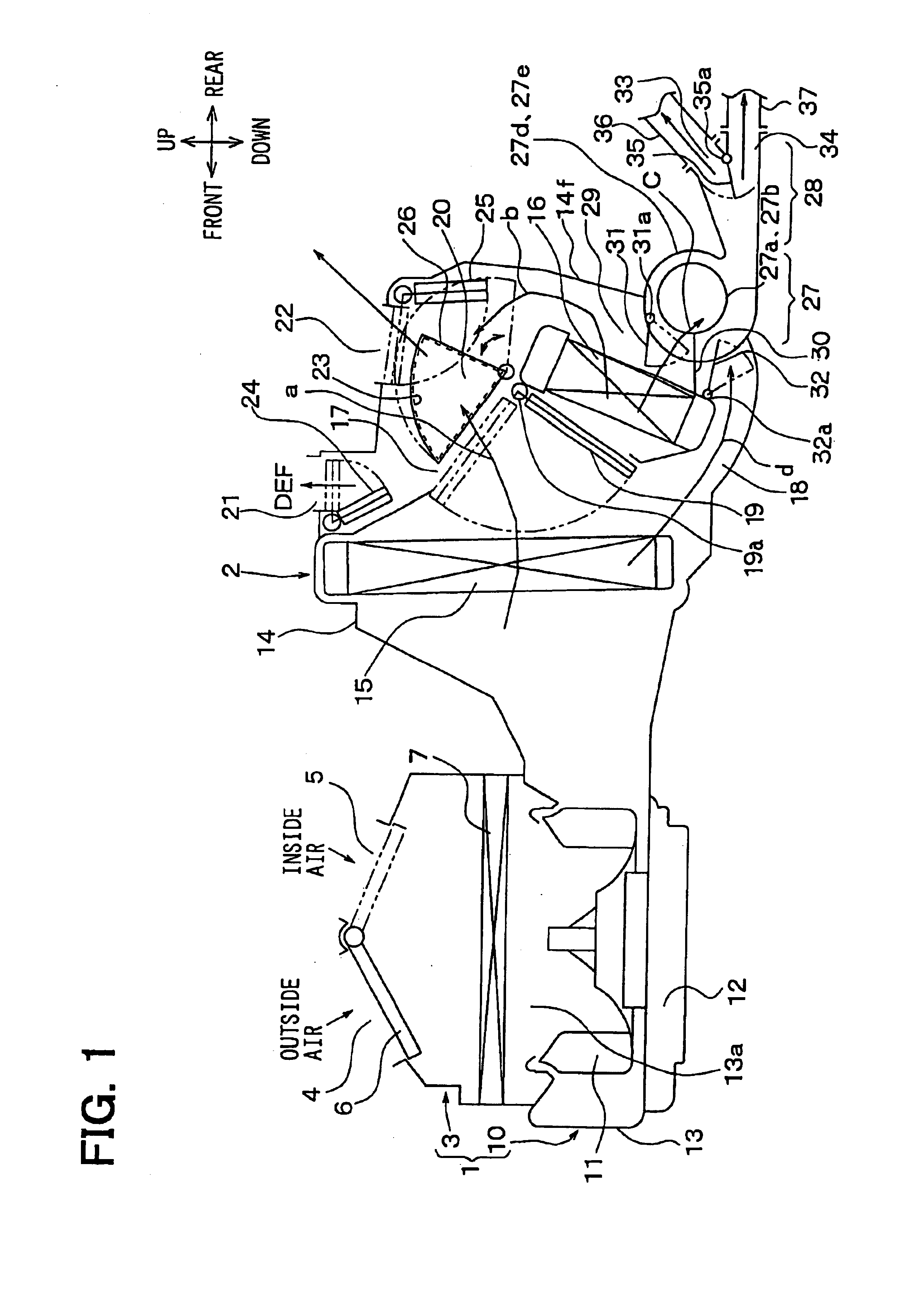
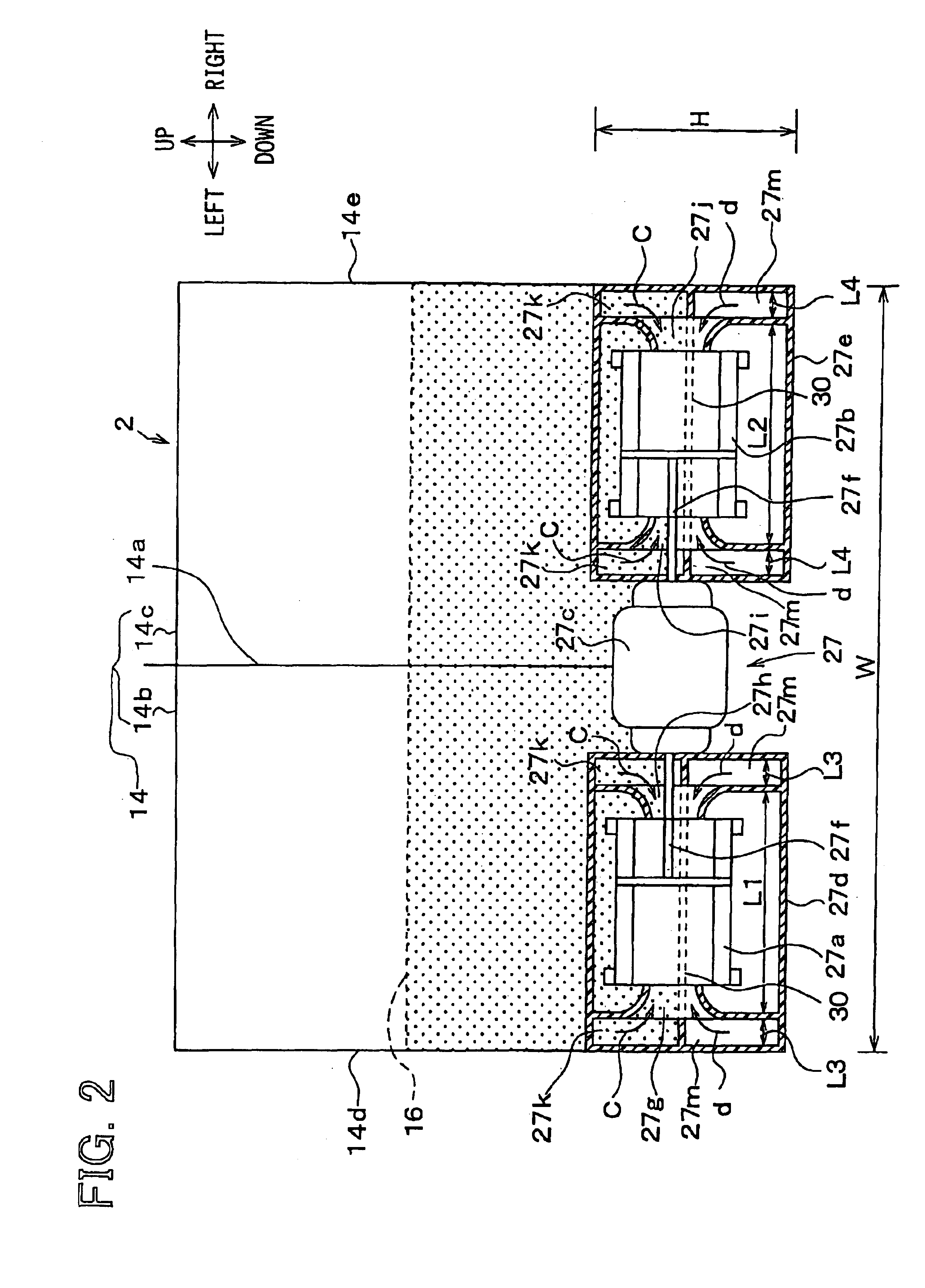
[0024]An interior air conditioning device shown in FIG. 1 is broadly constructed of a blower unit 1 and a heat exchange unit 2. In FIG. 1 and FIG. 2, arrows showing “up and down”, “front and rear”, and “left and right” indicate directions in a state where the heat exchange unit 2 is mounted in a vehicle, respectively. In FIG. 1, for convenience of preparing a drawing, the blower unit 1 is arranged on the front side of the vehicle of the heat exchange unit 2, but in reality, the blower unit 1 is arranged at an offset position in the lateral direction (i.e., right-left direction) of the vehicle of the heat exchange unit 2. That is, the heat exchange unit 2 is arranged nearly at the center in the lateral direction of the vehicle inside an instrument panel (i.e., dashboard) in the passenger compartment. The blower unit 1 is arranged to be offset to a front passenger's seat...


PUM


Abstract

A vehicle air conditioner includes a main blower and a sub-blower for blowing air into a passenger compartment. The main blower is disposed to blow conditioned air in a front air passage toward a front seat area in the passenger compartment, and the sub-blower is disposed in a rear air passage having an air flow resistance larger than that in the front air passage so that a part of air blown by the main blower is blown by the sub-blower toward a rear seat area in the passenger compartment through the rear air passage. In the air conditioner, an air amount blown by the sub-blower is controlled to be increased in accordance with a decrease of an air amount blown by the main blower. Therefore, automatic control of the air amount blown by the sub-blower can be accurately performed.

Description

CROSS REFERENCE TO RELATED APPLICATION[0001]This application is based on Japanese Patent Application No. 2002-326869 filed on Nov. 11, 2002, the disclosure of which is incorporated herein by reference.BACKGROUND OF THE INVENTION[0002]1. Field of the Invention[0003]The present invention relates to a vehicle air conditioner having a main blower and a sub-blower, which can perform air-conditioning of a plurality of different areas in a passenger compartment by using a single air conditioning unit. More particularly, the present invention relates to a control operation of the main blower and the sub-blower, with an automatic control of the sub-blower.[0004]2. Related Art[0005]There have been proposed various kinds of vehicle air conditioners each of which performs air-conditioning of a plurality of different areas, specifically, a front seat area and a rear seat area in a passenger compartment by using a single air conditioning unit.[0006]For example, in a vehicle air conditioner disclo...

Claims


Application Information

Patent Timeline
Patent Type & Authority Patents(United States)
IPC IPC(8): B60H1/00
CPCB60H1/00064B60H1/00828B60H2001/00099B60H2001/00107B60H2001/002
Inventor ITO, KOJITOKUNAGA, TAKAHIROSHINDO, TOMOHIDEOKUMURA, YOSHIHIKO
Owner DENSO CORP
Why Eureka
Try Eureka