Heat pump system

a heat pump and heat pump technology, applied in the direction of machines using solar energy, light and heating apparatus, machine operation mode, etc., can solve the problems of high energy cost and environmental concerns, require more energy efficient mechanisms, and large energy consumption of tasks

Inactive Publication Date: 2005-07-12
POWER ANYWHERE
View PDF32 Cites 39 Cited by
  • Summary
  • Abstract
  • Description
  • Claims
  • Application Information

AI Technical Summary

Problems solved by technology

High energy costs and environmental concerns over the generation of pollution require more energy efficient mechanisms for heating and cooling interior spaces.
Most of the prior art devices that accomplish this task are known to consume large amounts of energy (usually electrical energy), and are inefficient in both the cooling and heating modes.
One drawback of the '937 patent is that the system requires a mechanical compressor to compress the vaporized refrigerant being sent to the heat exchanger.

Method used


Image

  • Heat pump system
  • Heat pump system
  • Heat pump system

Examples


Embodiment Construction

[0021]Reference will now be made in detail to the drawings. Wherever possible, the same reference numbers will be used to refer to the same or like parts.

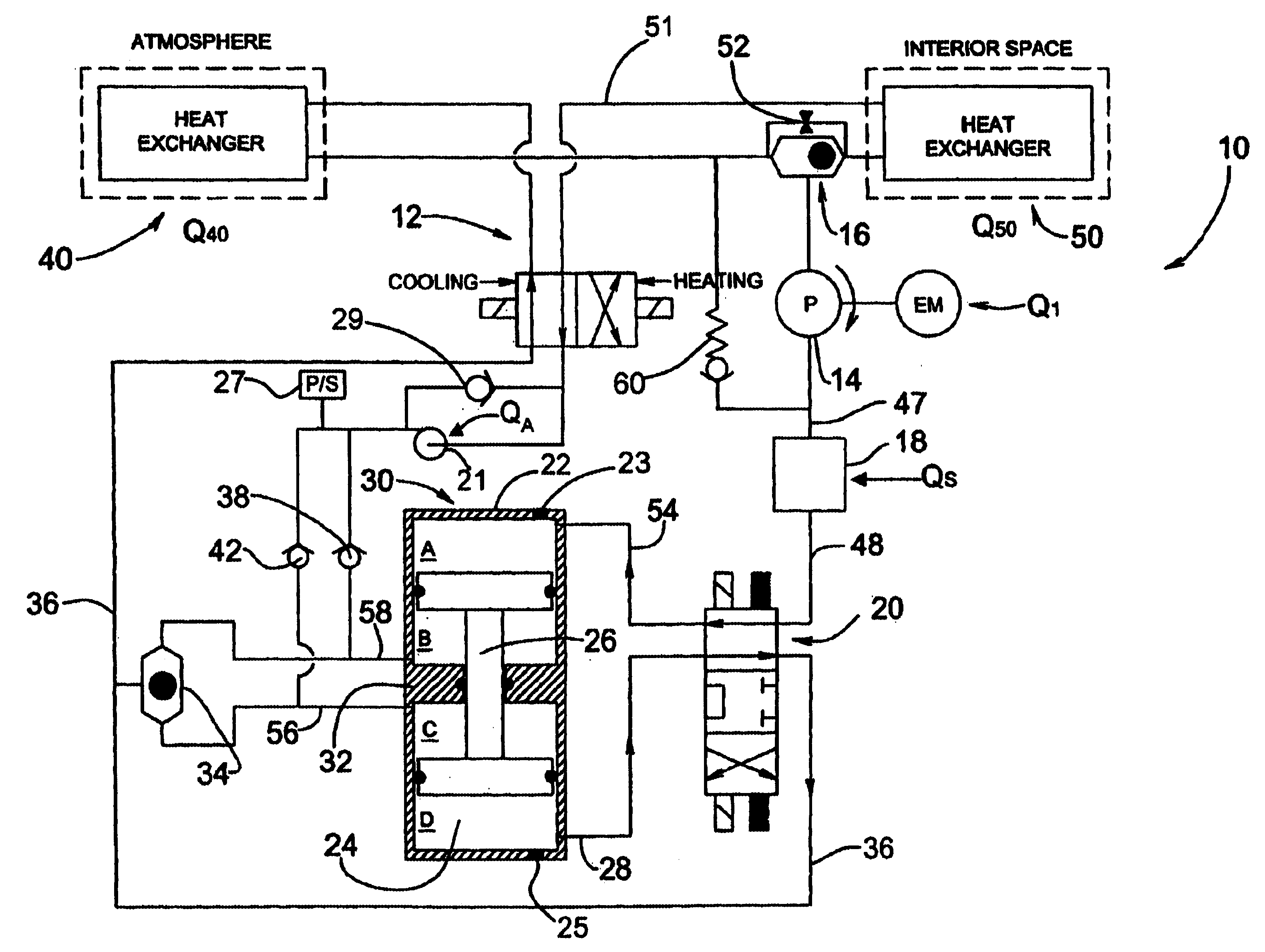
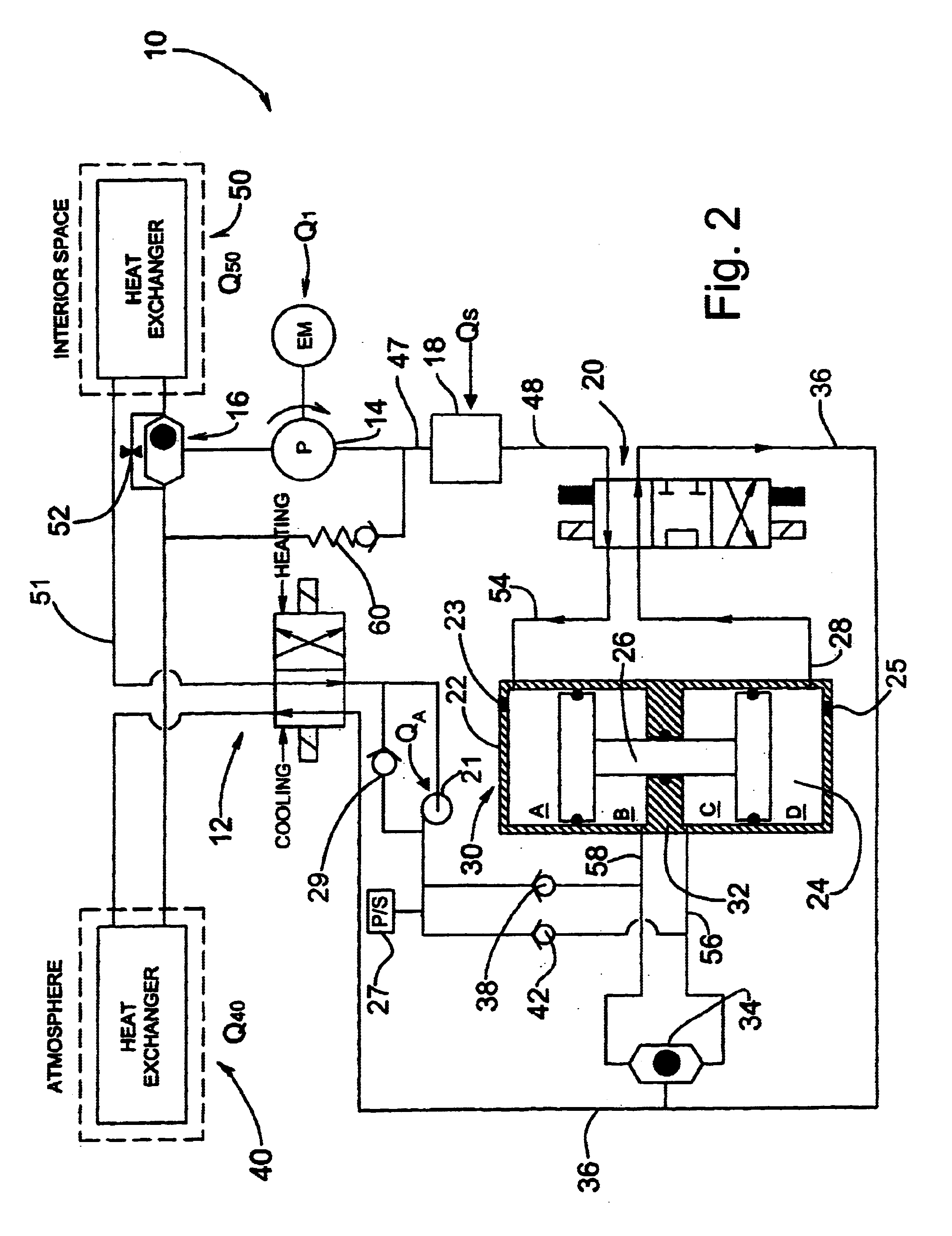
[0022]FIG. 2 depicts a heat powered heat pump system 10 in accordance with the present disclosure. As shown, the heat pump system 10 can cool an interior space, and by reversing the operation cycle, can also be used to heat an interior space. If the heat pump system 10 is used only for cooling or only for heating, certain components, such as a cooling / heating switch and a valve assembly can be altogether eliminated from the heat pump system 10. Further, heat pump system 10 is readily scalable, making it applicable to cooling and heating uses in large spaces as well as smaller volumes. For example, heat pump system 10 can be readily carried on board vehicles with their associated space limitations.

[0023]The heat pump system 10 will now be described by way of its operation. To initiate operation of heat pump system 10, an electric mo...


PUM


Abstract

A method and system for heating a space includes circulating refrigerant in a closed loop system having a first heat exchanger and a second heat exchanger. The circulating step includes pressurizing liquid refrigerant to a first pressure and heating the liquid refrigerant in a third heat exchanger to form a refrigerant vapor. The method further includes compressing refrigerant by a compressor to a second pressure, wherein the compressor is at least partially driven by refrigerant vapor received from the third heat exchanger, and supplying one of the first and second heat exchangers with refrigerant from the compressor. The method further includes supplying refrigerant from the other of the first and second heat exchangers to the compressor and selectively supercharging the refrigerant supplied to the compressor from the other of the first and second heat exchangers.

Description

FIELD OF THE INVENTION[0001]The present invention relates to a new and improved heat pump system and method of cooling or heating a space. More particularly, the present invention relates to a method and apparatus for driving and controlling a heat pump system.BACKGROUND[0002]High energy costs and environmental concerns over the generation of pollution require more energy efficient mechanisms for heating and cooling interior spaces. Utilizing renewable energy resources and, in some cases, waste heat from any number of sources improves energy efficiency. Mechanisms that use energy must be easily adapted to a number of different energy sources without the need for expensive or customized adaptors.[0003]The interior spaces that require heating and cooling are not limited to living and working environments, but also extend to spaces involved in transportation for humans and perishable commodities. The method of providing heating and cooling must be economical, efficient to manufacture, ...

Claims


Application Information

Patent Timeline
Patent Type & Authority Patents(United States)
IPC IPC(8): B60H1/32F25B1/10F25B13/00F25B27/00B60H1/00
CPCB60H1/3223F25B1/10F25B13/00F25B27/005F25B2700/06F25B2700/1933
Inventor RATLIFF, FRANK W.
Owner POWER ANYWHERE
Why Eureka
Try Eureka