Cable routing and affixment apparatus

a cable and cable technology, applied in the field of cable routing and affixing apparatus, can solve the problems of difficult task, corner, support beam, cable cannot be run in a straight line, etc., and achieve the effect of safely routing cables

Inactive Publication Date: 2005-07-12
THOMAS JONATHAN P
View PDF12 Cites 29 Cited by
  • Summary
  • Abstract
  • Description
  • Claims
  • Application Information

AI Technical Summary

Benefits of technology

[0012]An object of the present invention is to provide a device for safely routing cables around obstacles and corners during installation.
[0013]Another object is to provide a device that can be used for easy insertion of cables, to route cables during installation, and then be easily removed when no longer needed.
[0015]The cable guide of the present invention provides a means for containing and routing cable through awkward areas, such as bends and around obstacles and areas, which are hazardous to cable integrity. This is especially desirable in a building where it is desired to keep cables at the ceiling rather than allowing loops of cables to hang.
[0020]The tube ends are flared to facilitate pulling cables through to minimize chafing of the insulation. The tube ends are also designed with a cable retainer to temporarily encircle a cable in order to retain the cable while being pulled through. Four retention methods are contemplated:

Problems solved by technology

The vast majority of the time, there are obstacles, such as corners, support beams, suspended ceiling components, etc.
Obstacles mean that the cable cannot be run in a straight line, but must be routed around the obstacle.
Making the task more difficult is that, because these obstacles are either not visible, not easily accessible, or obstructed, attention has not been paid to making them safe during initial construction.
Typically there are abrasive edges or burrs that can wreak havoc on a cable as it is pulled across the obstacle.
There are currently no satisfactory temporary means for routing cables through obstacles and around corners.
Feeding large cable bundles through this guide is difficult and may be prohibitive.
Additionally, disassembly is time consuming.
Besides being mechanically complicated, it cannot be used to guide cables through ceilings, because of both its bulk and the fact that it does not have a means to temporarily mount it to building supports in a manner that is appropriate for ceiling routing.
They all mount to the junction box and do not disclose a means for independent mounting.
This product is mechanically complicated with a series of rollers circumferentially surrounding the cable path to provide a very narrow point of support.
Therefore, it is not suitable for those installations where bend radius is important, such as the routing of optical cables as the Optical fibers could become damaged or non-operational due to an excessively sharp bend.

Method used


Image

  • Cable routing and affixment apparatus
  • Cable routing and affixment apparatus
  • Cable routing and affixment apparatus

Examples


Embodiment Construction

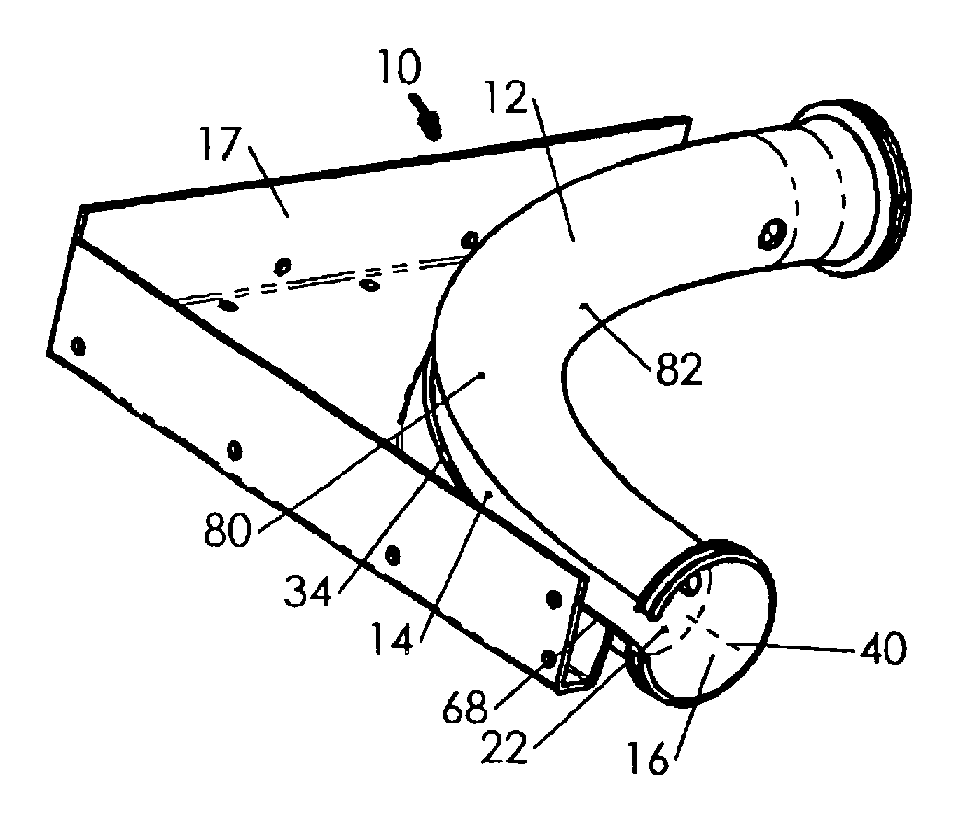
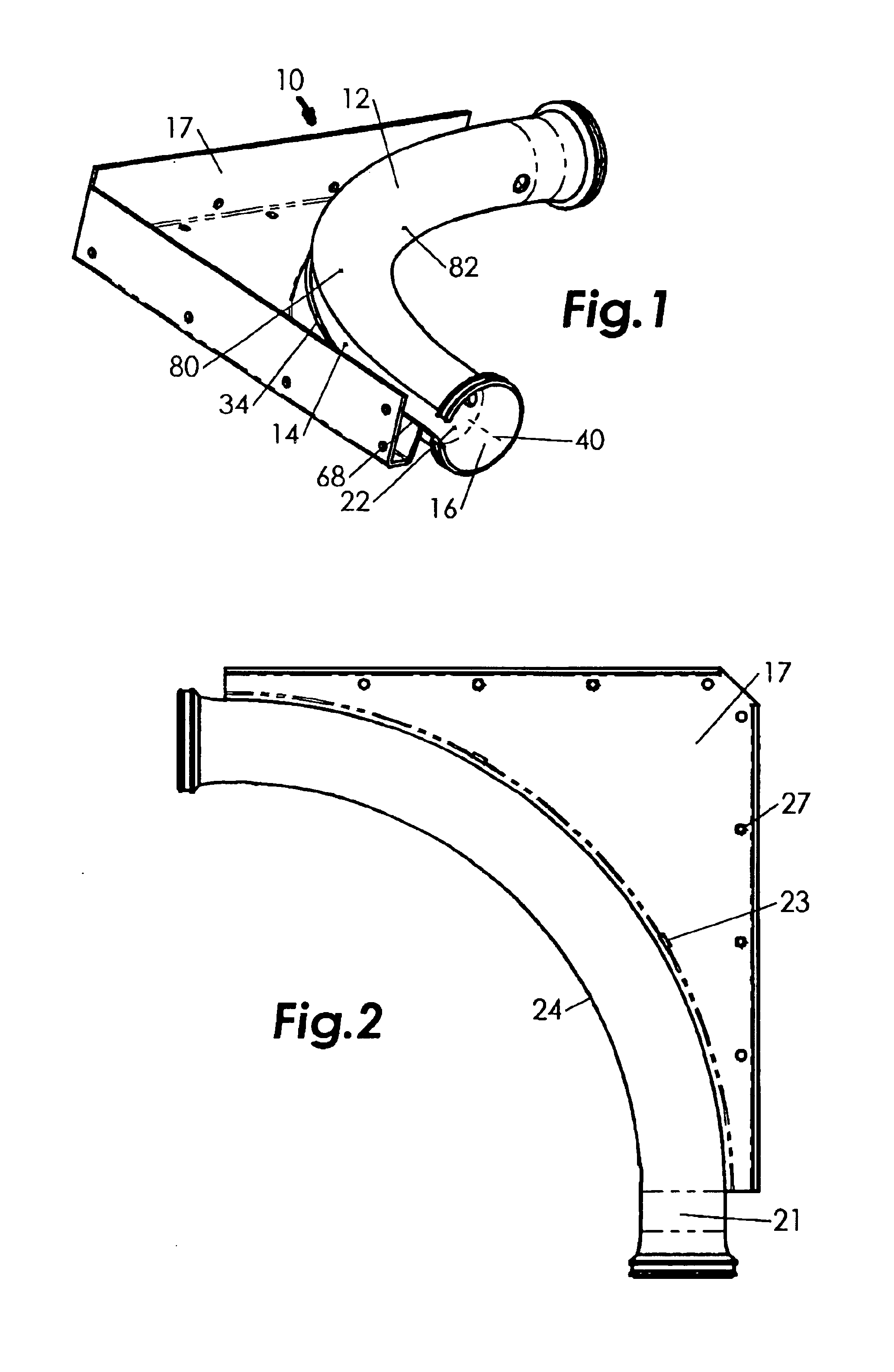
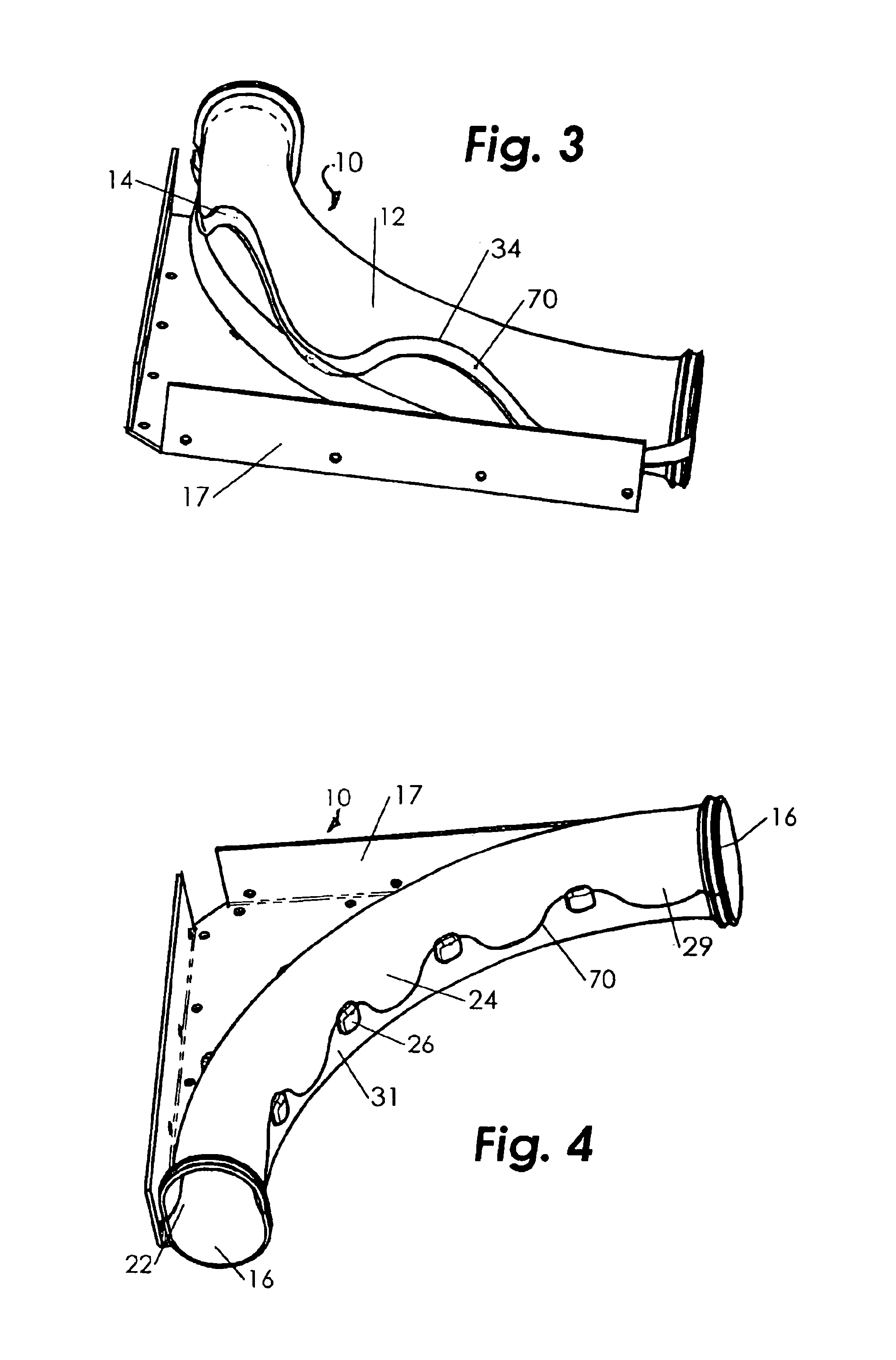
[0044]The cable routing guide and bracket (the “guide”) of the present invention is shown in the figures. FIGS. 1 and 2 represent one variant of the preferred embodiment wherein the guide 10 comprises a tube 12 with a slot 14, flared ends 16, an optional straight section 21 and a mounting hanger 17.

[0045]The tube 12 is a hollow cylinder composed preferably of a rigid plastic including materials having a friction reducing quality. It may also be composed of cast or stamped metals or alloys, such as aluminum or steel. It also may be comprised of single or multiple pieces that are manufactured separately and then permanently or temporarily fastened together. The cross-sectional shape of the tube 12 may be round, oval, or any other shape appropriate for the particular application. The inside wall 22 is smooth so that cables can be slid easily through the guide 10 without being snagged or otherwise obstructed by the guide itself. Optionally, the inner surface is coated with a friction-re...


PUM


Abstract

A cable guide for containing and routing cables through building. One version of the guide includes a rigid hollow tube with a slot, flared ends, and mounting hangers while a second embodiment encompasses a tube axially split in two sections. The tube has a bend that traverses any angle necessary for a particular application, typically between 0° and 180°. There may be more than one bend. The cable is inserted and removed from the guide through the straight or helical slot, which extends the full length of the tube or by separating the clamshell. The tube ends are flared. Each end optionally has a cable retaining annular groove for a cable tie or the like. An additional embodiment has a hinged flap to perform the same function. The hangers are tabs that extend from the tube and spaced out along the length of the tube or a bracket like structure which provides a means for attachment.

Description

CROSS REFERENCES TO RELATED APPLICATIONS[0001]This application arises from and claims priority from Provisional Patent Applications 60 / 165,406 for SPLIT CABLE PULLING ACCESORIES filed on Nov. 13, 1999 and 60 / 195,466 for CABLE ROUTING GUIDE AND BRACKET filed on Apr. 10, 2000.STATEMENT REGARDING FEDERALLY SPONSORED RESEARCH OR DEVELOPMENT[0002]Not applicableMICROFICHE APPENDIX[0003]Not ApplicableBACKGROUND OF THE INVENTION[0004]1. Field of the Invention[0005]The present invention relates to electrical and optical cables, more particularly, to apparatus useful for routing electrical and optical cables as well as flexible tubing through buildings, structures, and the like.[0006]2. The Prior Art[0007]Occasionally a cable or bundles of cables, be they electrical or optical, must be strung through a building, typically along an open ceiling or above a suspended ceiling. Generally, the cable is pulled from one intermediate location to another until the ends of the cable are at their intende...

Claims


Application Information

Patent Timeline
Patent Type & Authority Patents(United States)
IPC IPC(8): B65H59/00H02G1/06H02G1/08
CPCH02G1/06H02G1/08
Inventor THOMAS, JONATHAN P.
Owner THOMAS JONATHAN P
Why Eureka
Try Eureka