Wire holding basket

a technology of wire holding basket and wire holding plate, which is applied in the direction of insulated conductors, cables, conductors, etc., can solve the problems of easy bending of wires for power supplies in the bent portion, unavoidable enlargement of installation space for wires and the like, and complicated driving mechanisms, etc., to achieve simple structure, simple operation, and stable mounting

Inactive Publication Date: 2016-09-08
SUMITOMO WIRING SYST LTD
View PDF4 Cites 4 Cited by
  • Summary
  • Abstract
  • Description
  • Claims
  • Application Information

AI Technical Summary

Benefits of technology

[0013]The wire holding rib may include a flat plate portion projecting from a bottom surface of the wire accommodating recess toward an upper opening and extending along the extending direction of the wire accommodating recess. Additionally, the engaging protrusion may project from a tip part of the flat plate portion toward both widthwise sides. Accordingly, the wire accommodated and held on the wire holding bracket that slidingly moves relative to the guide rail can be held reliably by a simple structure of providing the projecting wire holding ribs having a T-shaped cross-sectional shape as a whole in the wire accommodating recess. In addition, since the engaging protrusion is provided at opposite sides of the tip part of the flat plate portion, wires can be supported more stably along the opposite side surfaces of the flat plate portion.
[0014]The slide bracket may include an extending plate portion arranged to face one side surface of the guide rail, whereas the mounting portion may include a flat main body portion to be placed on an outer surface of the extending plate portion and an engaging claw portion projecting from a peripheral edge part of the flat main body portion toward the extending plate portion and configured to press the flat main body portion into contact with the outer surface by being engaged with the extending plate portion. Accordingly, the wire holding bracket can be mounted stably on the slide bracket merely by a simple operation of placing the flat main body portion on the extending plate portion of the slide bracket arranged to face the one side surface of the guide rail and engaging the engaging claw portion with the extending plate portion. In addition, the mounting portion can be configured into a flat shape composed of the flat main body portion and the engaging claw portion. Thus, the mounting portion advantageously can be mounted with a stable holding force of the mounting portion on the slide bracket ensured even in a narrow area between the supporting body and the movable body.
[0015]The wire for power supply is formed of a curl cord including a spiral portion routed expandably and contractibly in the extending direction of the guide rail, and the wire main body holding portion is provided on the tip of an extending portion extending from the mounting portion in an expanding direction of the spiral portion of the curl cord. Accordingly, a separate device such as a spool is not necessary unlike in a conventional structure and the wire for power supply having a length capable of covering a movable range of the movable body can be routed in a space-saving manner. Further, the wire main body holding portion of the wire holding bracket is provided on the tip of the extending portion extending in the expanding direction of the spiral portion of the curl cord. Thus, a length of the curl cord routed along the extending direction of the guide rail can be advantageously ensured by holding the end part of the spiral portion of the curl cord in the expanding direction on the wire main body holding portion. Note that an extending length of the extending portion can be adjusted easily to various movable bodies having different movement amounts by being appropriately changed in accordance with a length of the spiral portion of the curl cord that changes depending on the movement amount of the movable body.
[0016]An end part of the spiral portion of the curl cord may be fixed to the wire main body holding portion, whereas an inner wire obtained by removing a coating of the curl cord is accommodated and arranged in the wire accommodating recess. Accordingly, the wire for power supply can be routed advantageously even if an area around the guide rail is narrow.
[0017]The wire accommodating recess may include a bent portion in which an extending direction changes. Additionally, a cover configured to cover an upper opening of the wire accommodating recess may be mounted near the bent portion. There is a high possibility that the wire for power supply bent in the bent portion is detached easily and interferes with other members. However, mounting the cover to cover the upper opening of the wire accommodating recess near such a bent portion can reliably prevent having the wire protrude and interfere with other members.
[0018]The wire holding bracket of the present invention includes the wire main body holding portion and the wire end holding portion respectively projecting from the mounting portion to be mounted on the slide bracket toward the one and the other sides in the transverse direction of the guide rail. This enables the wire for power supply to be routed from the one side toward the other side across the guide rail in the transverse direction. Thus, the wire for power supply can be secured space-efficiently, skillfully using the space originally provided around the guide rail. In addition, by providing the wire accommodating recess, the wire for power supply can be routed safely in the movable area by preventing the interference of the guide rail, surrounding other members such as the driving mechanism and the wire. Therefore, the wire for power supply can be routed safely by space-efficiently preventing interference with other members even in a narrow clearance between the supporting body and the movable body.

Problems solved by technology

However, in the wire routing disclosed in US Patent Publication No. 2013 / 0047513), it is necessary to install the large-size spool and a longitudinal accommodation rail for guiding the flexible cable to avoid interference with other members on the fixed window, thereby presenting a problem that the enlargement of an installation space for the wire and the like is unavoidable.
Further, a rear window system of an automotive vehicle which is vertically slid to be opened and closed is disclosed in Japanese Unexamined Patent Publication No. 2007-253866, but a complicated driving mechanism is arranged between a movable body and a supporting body.
There is a high possibility that the wire for power supply bent in the bent portion is detached easily and interferes with other members.

Method used


Image

  • Wire holding basket
  • Wire holding basket
  • Wire holding basket

Examples


Embodiment Construction

[0026]Hereinafter, an embodiment of the present invention is described with reference to the drawings.

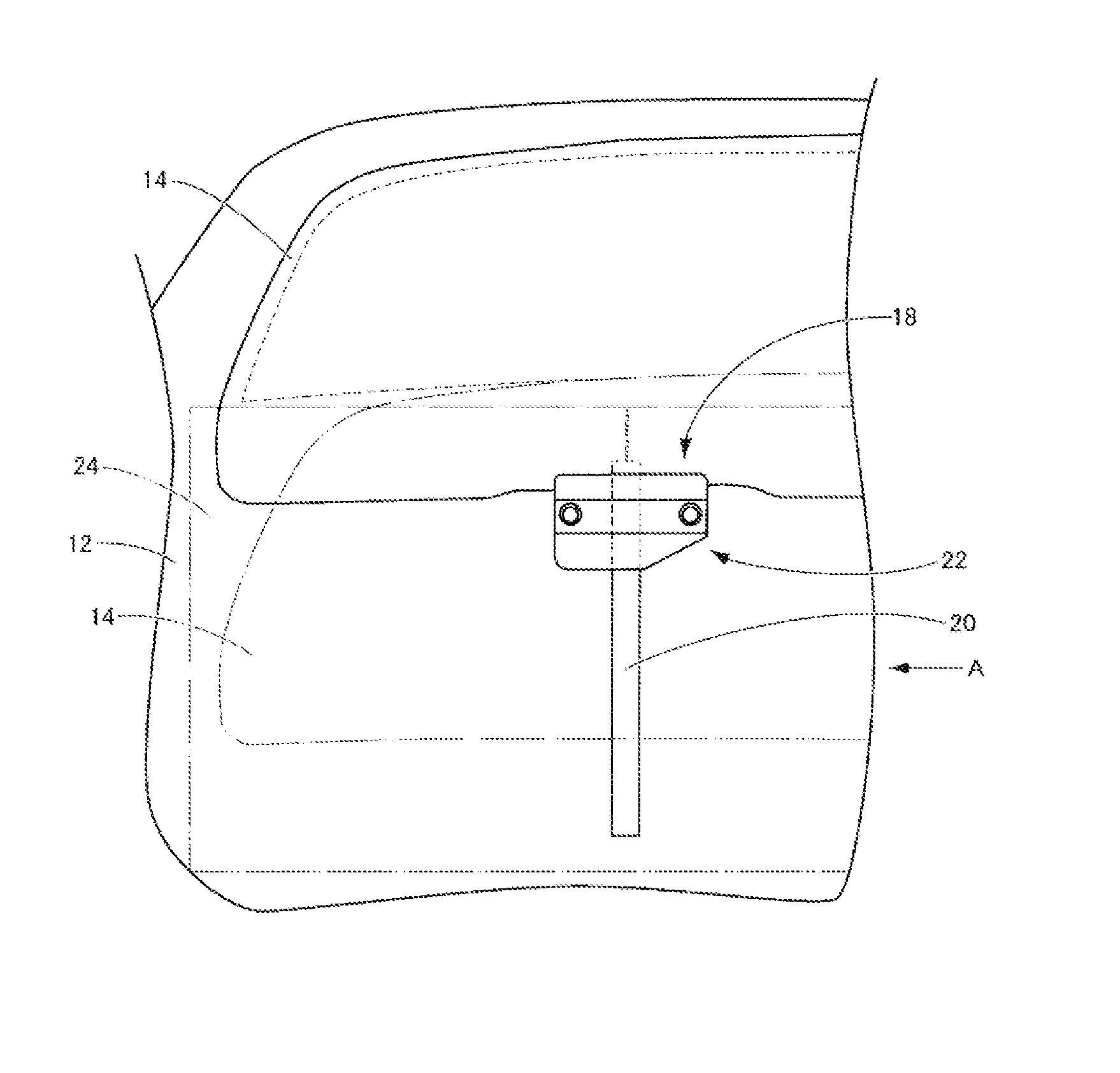
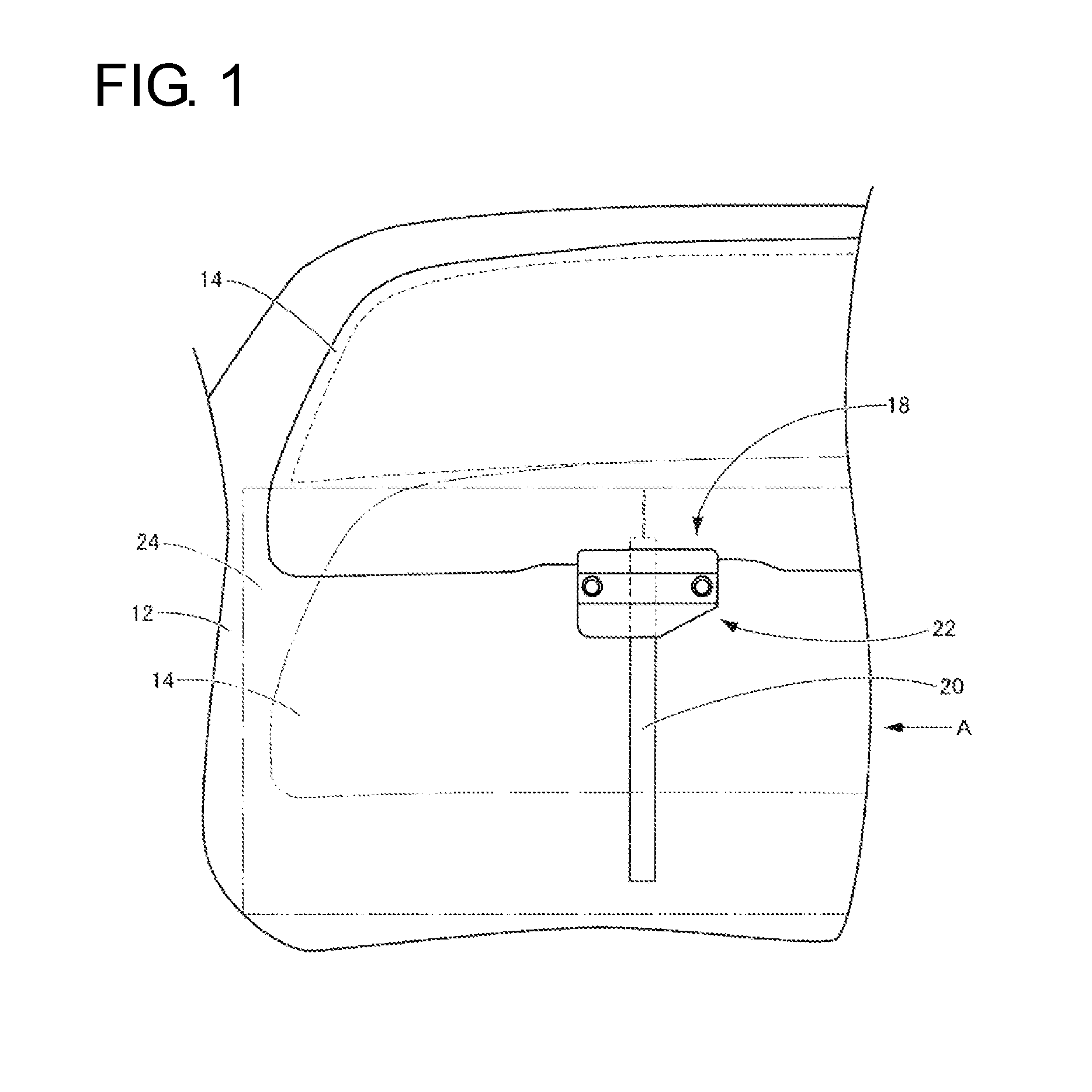
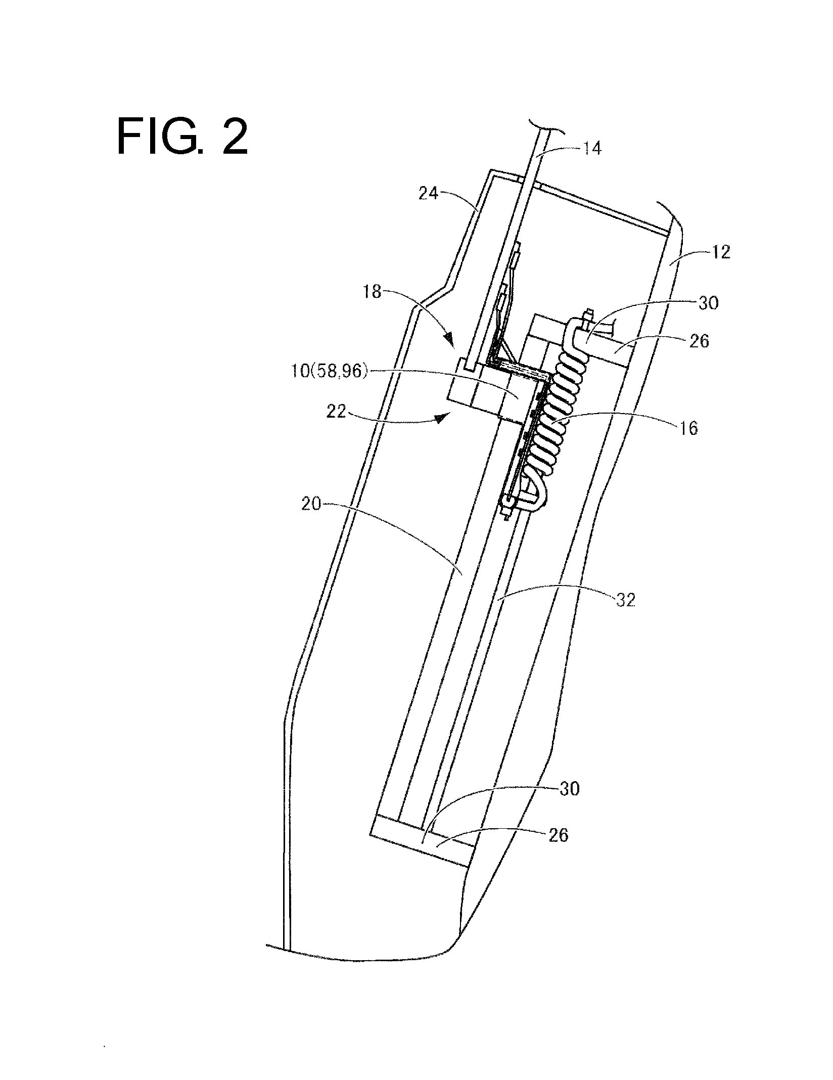
[0027]FIGS. 1 to 7 show a state where a curl cord 16 as a wire for power supply is routed between a vehicle 12 as a supporting body and a rear window 14 as a movable body displaceably mounted relative to the vehicle 12 using a wire holding bracket 10 as one embodiment of the present invention. More specifically, as shown in FIG. 1, a sliding mechanism 18 entirely slidingly displaceable in a vertical direction of the vehicle 12 is mounted in the rear window 14. As shown in FIGS. 2 and 3, the sliding mechanism 18 includes a guide rail 20 extending in a sliding direction (vertical direction in FIGS. 2 and 3) of the rear window 14 and fixed to the vehicle 12, a slide bracket 22 slidably engaged with the guide rail 20 and the curl cord 16 arranged along the guide rail 20. Since the spirally wound curl cord 16 is free to expand and contract during a sliding movement from a state shown in ...


PUM

PropertyMeasurementUnit
poweraaaaaaaaaa
flexibleaaaaaaaaaa
areaaaaaaaaaaa

Abstract

A wire holding bracket space-efficiently and safely routes a wire for power supply on a movable body (14). The wire holding bracket includes a mounting portion (58) mounted on a slide bracket (22). A wire main body holding portion (48) projects from the mounting portion (58) toward one side in a transverse direction of a guide rail (20). A wire end holding portion (66) projects from the mounting portion (58) toward the other side in the transverse direction of the guide rail (20) and extends toward a power supply unit (68) of a movable body (14). A wire accommodating recess (70) extends from the wire main body holding portion (48) to the wire end holding portion (66) through the mounting portion (58). The mounting portion (58) is slidable relative to the guide rail (20) together with the slide bracket (22) by being mounted on the slide bracket (22).

Description

BACKGROUND[0001]1. Field of the Invention[0002]The present invention relates to a wire holding bracket used to route a wire for power supply arranged between a supporting body and a movable body displaceably mounted relative to the supporting body.[0003]2. Description of the Related Art[0004]Conventionally, an automotive vehicle includes many movable bodies such as a back door and a rear window displaceably mounted relative to a supporting body such as a vehicle body and free to open and close. In the case of mounting an electrical device such as a hot wire in the movable body, power is supplied to the electrical device by routing a wire for power supply between the supporting body and the movable body.[0005]Such a wire routed between the supporting body and the movable body needs to be routed, taking into account a movable range of the movable body. For example, an example of wire routing for installing a spool obtained by reeling a strip-like flexible cable for power supply on a f...

Claims


Application Information

Patent Timeline
Patent Type & Authority Applications(United States)
IPC IPC(8): H01B7/06B60R16/02H02G3/04
CPCH01B7/065B60R16/02H02G3/04H02G11/006B60R16/0215B60R16/027
Inventor WATA, MAKOTO
Owner SUMITOMO WIRING SYST LTD
Why Eureka
Try Eureka