Fluid diverter system for a drilling facility

a technology of flue gas diverter and well, which is applied in the direction of drilling, borehole/well accessories, construction, etc., can solve the problems of more difficult for drillers to detect a kick early, gas may inadvertently enter the riser, and design should not allow the diverter to completely shut-in the well

Active Publication Date: 2015-10-20
MHWIRTH
View PDF29 Cites 1 Cited by
  • Summary
  • Abstract
  • Description
  • Claims
  • Application Information

AI Technical Summary

Benefits of technology

[0023]It is thus provided that any gas that may have entered the riser after the BOP is shut-in on a kick is vented safely overboard and at the same time mud can be returned to the system in a safe way.
[0024]It also provide that “Drilled gas” can be routed safely to the MGS separator from the diverter keeping the diverter element closed preventing gas breaking out through the diverter housing and escaping on drill floor. When running the system in degasser mode, it will allow the gas cut mud to go through a two stage separating process. The MGS will take out the gas that normally would escape to drill floor and the shakers, while the second stage is done by the degassers in the mud treatment tanks. Degassers are used to separate entrained gas bubbles in the drilling fluid which are too small to be removed by the MGS.

Problems solved by technology

A kick is a situation where hydrocarbons, water, or other formation fluid enters the wellbore during drilling, because the pressure exerted by the column of drilling fluid is not great enough to overcome the pressure exerted by the fluids in the formation being drilled.
As the industry is going to deeper water it has been more difficult for the drillers to detect a kick early because the gas will be in liquid or dense phase, due the static pressure at sea level (where the BOP is located).
Gas may inadvertently enter the riser while drilling at any depth when the BOP is shut-in on a kick.
Again, the design should not allow the diverter to completely shut-in the well.”
The dangerous parts of this design is that the flow rate of mud returning from the riser is much higher than the design capacity of the MGS, resulting in filling of MGS and vent line.
In either one of these designs, the dangerous part is that the available time in which to take the appropriate action, i.e. before the vent line of the MGS is completely filled, is very limited.
At the time when high level in the MGS or high pressure in the diverter have been reached, the mud returning from the riser is in a highly accelerating mode and the time available for opening the diverter valve is very limited.
A slug of heavy mud accelerating up the MGS vent line followed by a two phase flow and finally a large gas release will create an increased pressure in the diverter housing and possible leakage in the slip joint resulting in gas being release under the rig at the slip joint connection.
A worst case scenario of such an event is the Deepwater Horizon disaster.

Method used


Image

  • Fluid diverter system for a drilling facility
  • Fluid diverter system for a drilling facility
  • Fluid diverter system for a drilling facility

Examples


Embodiment Construction

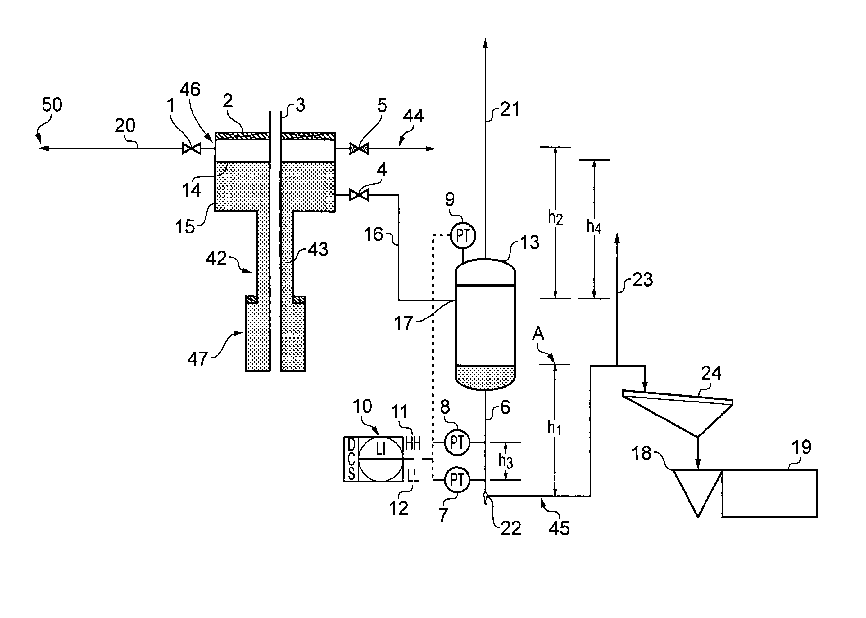
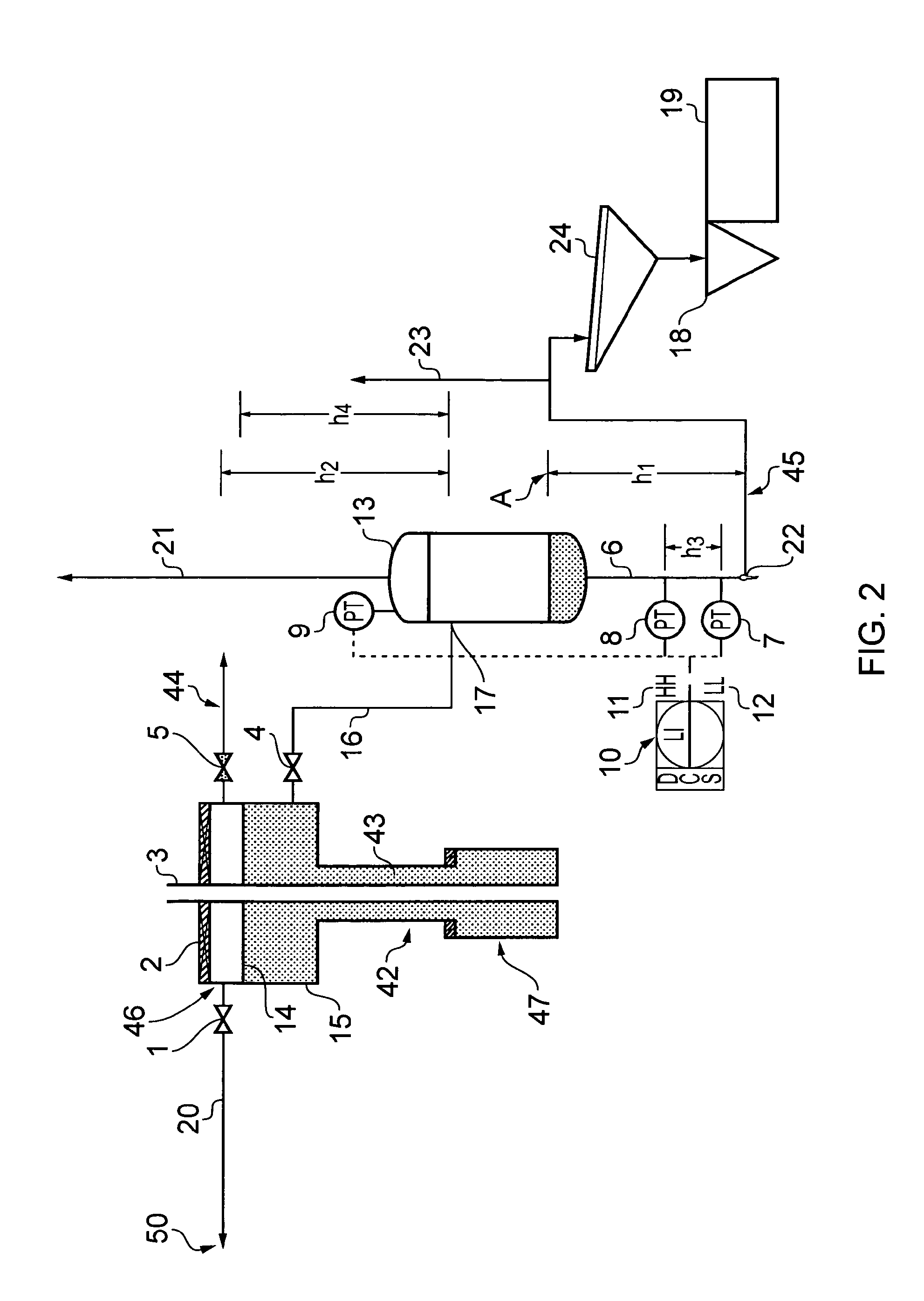
[0030]A drill string 3 extends between a topsides drill floor (not shown) and a seabed BOP (not shown), extending in a telescopic so-called “slip-joint”42 and a marine riser 47 thus defining an annulus 43. This arrangement is well known in the art, and need therefore not be described further.

[0031]A diverter housing 15 is arranged in fluid communication with the annulus 43 and a diverter line 20 which extends from an outlet 46 in the diverter housing and to an outlet 50 at an overboard location. A diverter housing normally has two diverter lines, extending to the port and starboard sides, respectively, of the vessel, such that the diverter line on the leeward side may be used, as explained above. For illustration purposes, however, only one diverter line is shown. A diverter valve 1 is arranged in each diverter line 20. In the figures, the diverter valve 1 is shown in an open state (white typeface).

[0032]The diverter housing 15 is also connected to the vessel's mud system (not shown...


PUM


Abstract

A fluid diverter system for a drilling facility comprises a diverter housing (15; 15′) fluidly connected to a tubular (3, 42, 43) extending to a subsea well. The diverter housing (15; 15′) comprising a movable diverter element (2) for closing off the diverter housing, a first fluid conduit (44) connected to a mud system and comprising a first valve (5), at least one second fluid conduit (20; 20′) leading from an outlet (46; 46′) in the diverter housing to an overboard location and comprising a second valve (1; 48), and a third fluid conduit (16) connected to a mud / gas separator (MGS) (13) and comprising a third valve (4). The MGS (13) is arranged below the outlet (50) of the diverter line, whereby riser fluids may be fed from the diverter housing (15) to the MGS (13) by means of gravity flow. The diverter valve (1; 48) on a leeward side of the drilling facility is configured to be open before the diverter element (2) closes around the tubular (3).

Description

FIELD OF THE INVENTION[0001]The invention relates to the extraction of hydrocarbons from subsea, subterranean, wells. More specifically, the invention relates to a system for handling fluids from a wellbore, as specified in the preamble of the independent claim 1.BACKGROUND OF THE INVENTION[0002]Diverter systems for use in subsea drilling into hydrocarbon wells are well known. Originally, diverter systems were installed on drill ships or semi-submersible drilling rigs in order to handle shallow gas when drilling with a marine riser on top hole sections before the Blow-Out Preventer (BOP) was installed. Today it is more common to drill the top hole sections with seawater or water based mud and with return to seabed or “riserless” return to the rig.[0003]Today, the main purpose of the diverter system is to handle gas that for some reason has entered the riser after the BOP is shut in on a so-called “kick”. A kick is a situation where hydrocarbons, water, or other formation fluid enter...

Claims


Application Information

Patent Timeline
Patent Type & Authority Patents(United States)
IPC IPC(8): E21B7/12E21B21/06E21B21/01E21B21/00E21B21/08
CPCE21B21/001E21B7/12E21B21/01E21B21/067E21B21/08
Inventor VAVIK, DAG
Owner MHWIRTH
Why Eureka
Try Eureka