System and method for securing power and communications cables and associated hardware within crown molding

a technology of power and communications cables and associated hardware, which is applied in the direction of flooring, covering/linings, construction, etc., to achieve the effects of preventing unsafe or sharp bends, facilitating safe routing, and securing and using

Active Publication Date: 2018-09-25
HOFFMAN JEREMY P +1
View PDF21 Cites 1 Cited by
  • Summary
  • Abstract
  • Description
  • Claims
  • Application Information

AI Technical Summary

Benefits of technology

[0020]The present invention facilitates safely routing, securing and using power and communications cabling within crown molding. The invention includes providing a safe path for electrical cables that inherently prevents unsafe or sharp bends that could otherwise damage the cables. This is particularly useful within crown molding, where most spaces within which crown molding is installed have corners. The invention creates a smoothly curving path or paths, with bends sized as needed, which inherently prevent damaging unsafe or sharp bends and route cables safely around what would otherwise be a sharp corner at the intersection of the rear surfaces of crown molding in an inside corner, or the sharp corner at the intersection of two walls in an outside corner. The invention also provides a safe method for cables to enter and exit the crown molding and any installed equipment and, where a cable path is enclosed, safe entry to that cable path.
[0021]The invention also provides a location within the molding, and a method for conveniently and safely securing, electrical and other associated hardware within the molding. Hardware and equipment can be installed in this location using simple screws or other fasteners in concert with the lever action of a pivot and socket behind the face of the crown molding to provide secure seating of the equipment without ever piercing or otherwise violating a cable path, and whose installation method never disturbs the face of the crown molding. Further, installed equipment remains visible and accessible from above and yet concealed and hidden from view to occupants of the room below.
[0023]This invention also provides a location to securely mount electronic devices and sensors through the decorative face of the molding. This is done by providing a dedicated area of the decorative face which is designed flat and without decorative curves for a set section of the profile, and providing a parallel plane of similarly flat surface on the rear of the decorative face of the molding. This dedicated area of parallel flat surfaces is placed deliberately between the communications cable routing path and the power cables routing path, providing secure and easy access to both. A secure location is particularly important to the deployment of a coordinated multi-camera array that leverages technology outside this invention to combine the output of multiple cameras usefully.
[0024]The invention provides for the entirety of cabling installation and routing and all associated equipment installations related to this invention to be installed. All of the benefits of this system and method are deployed after the entire crown molding system has been installed and secured using existing techniques and methods known in the art. Also, any changes or upgrades to the cabling, electrical equipment or systems installed using this invention can be executed with minimal or no modifications to the base crown molding system. In addition, all hardware and electrical equipment installed within and onto the base crown molding is readily visible and can be easily inspected, serviced and replaced as needed.

Problems solved by technology

Further, installed equipment remains visible and accessible from above and yet concealed and hidden from view to occupants of the room below.

Method used


Image

  • System and method for securing power and communications cables and associated hardware within crown molding
  • System and method for securing power and communications cables and associated hardware within crown molding
  • System and method for securing power and communications cables and associated hardware within crown molding

Examples


first embodiment

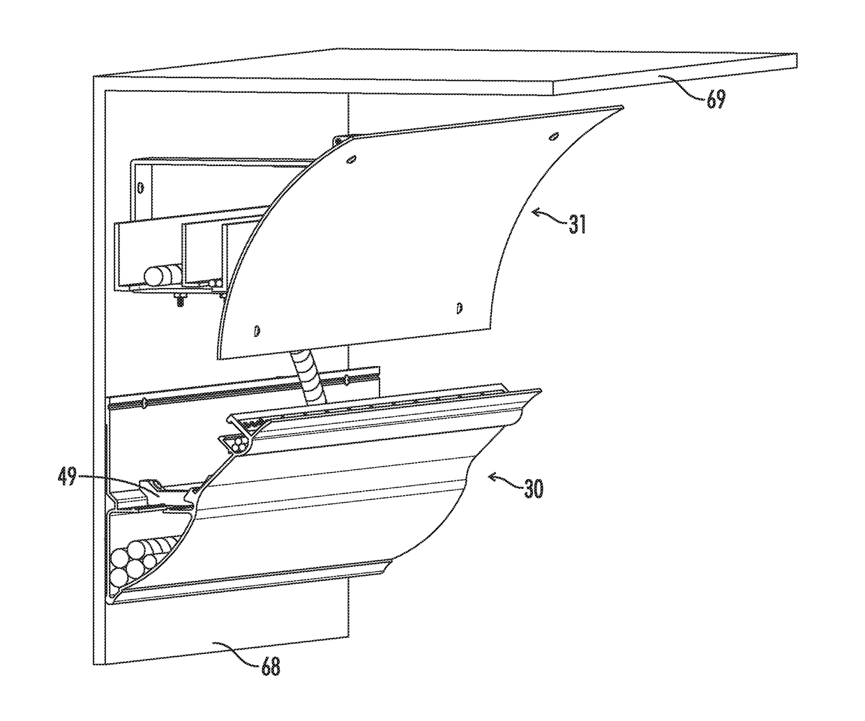
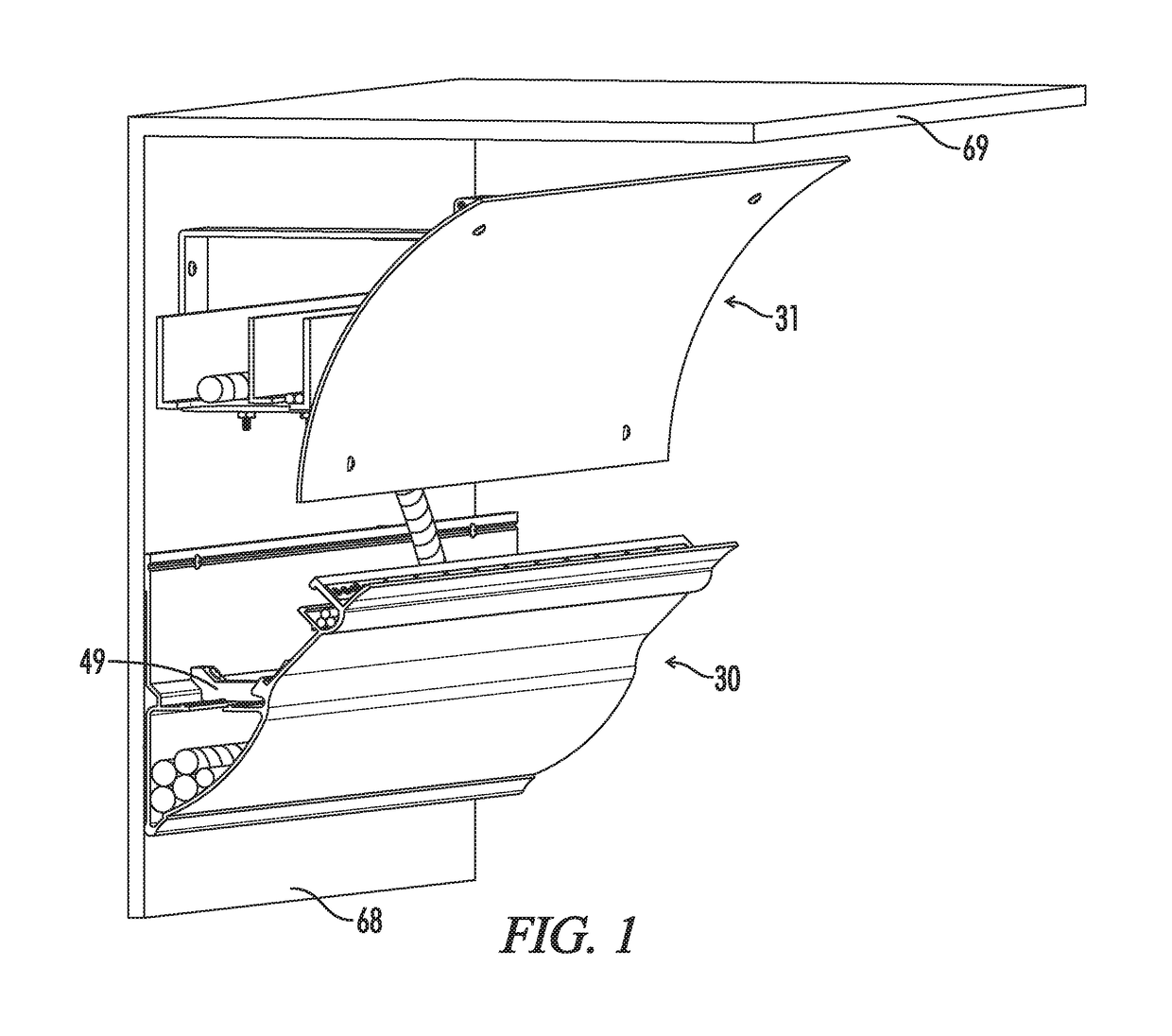
[0065]The structure of crown molding 30, light reflector assembly 31 and inside corner 84 has been described in this first preferred embodiment of the present invention. Crown molding 30, light reflector assembly 31 and inside corner 84 are the only three items detailed in the figures, where the three provide a representative and detailed view of the characteristics of this first preferred embodiment of this invention. However, they are not meant to be limiting by their inclusion. For example, the same principles of this first embodiment of this invention which are described in FIGS. 11-13 in view of inside corner 84, can be directly applied to an outside corner of the same system, where the curved cable paths protect cables from being pulled against the sharp corner of the wall instead of against the sharp corner of intersecting decorative faces, as does inside corner 84.

[0066]Referring now in particular to FIGS. 14 and 15 which illustrate a second preferred embodiment of the prese...

third embodiment

[0070]Referring now to FIGS. 22-26 in which the crown molding assembly of the present invention is shown, crown molding assembly 113 is comprised generally of a standard crown molding section 114, a molding installation block 117, and a hardware socket forming structure 123. Standard crown molding 114 has a decorative face 32, a rear surface 115, and a wall contact surface 116 which is angled downwardly from the lower end of rear surface 115. Standard crown molding 114 can be any profile of crown molding as long as the spring angle is that which the system is designed for, and the profile is above a minimum profile height. Molding installation block 117 includes a molding attachment surface 118 against which the rear surface 115 of molding section 114 is secured, a wall contacting surface 119, a bulkhead 50 having a surface angled favorably to accept a screw and provide favorable access for a screw driving tool, and a horizontal surface 120 extending between bulkhead 50 and the uppe...

second embodiment

[0079]As previously described, crown molding 30 is formed from fiber reinforced polymer (FRP) using the continuous process of pultrusion. FRP has favorably properties toward the deployment of an interconnected system of location beacons 75, notably that the FRP material is radio transparent, and freely passes radio signals to and from location beacons 75 from antenna 82 behind decorative face 32, allowing location beacons 75 to operate while remaining concealed behind decorative face 32. The elevated position of crown molding 30 on the wall combined with the positioning and design of antenna 82 are favorable to broadcasting and receiving signals from persons, devices and other enabled hardware within and travelling through the space, in addition to sending and receiving signals from other nearby location beacons 75. The installation process for a location beacon 75 is as follows. First, the installer identifies a location within a straight section of crown molding 30 where no other ...


PUM


Abstract

A system for crown molding that enables safely incorporating electrical and communications cabling within crown molding by creating one or more protected paths which inherently prevent overly sharp bends in crown molding corners and by mitigating damage from penetrating punctures through a decorated face designed to fracture when improperly penetrated by a screw or nail, and enables the secure installation of hardware either concealed within the molding or securely and favorably positioned through the decorative face to view or sense a room, and enables additional cable capacity that is concealed within a light reflector to increase lighting efficacy as well as power and data delivery capacity.

Description

FIELD OF THE INVENTION[0001]The present invention is directed to systems and methods for installing decorative molding in a building's interior and to making use of the spaces within that molding to safely carry electrical cables, electrical equipment and to provide lighting. In particular, LED lighting has been identified as an energy saving alternative for lighting, and has characteristics that make it ideal for deployment in a linear fashion, such as within crown molding. LED light sources are also well suited to providing indirect lighting, such as lighting a space by directly lighting a ceiling, which in turn indirectly lights the space. Indirect lighting such as ceiling directed LEDs within crown molding can also improve the quality of the light as LEDs are a very bright point source, and indirect lighting such as is reflected off of a ceiling will be inherently diffused and smoother. The present invention also addresses the need for communications cables to be provided and us...

Claims


Application Information

Patent Timeline
Patent Type & Authority Patents(United States)
IPC IPC(8): F16L3/00H02G3/04F16L3/22E04F19/04F16L3/26H02G3/06H02G3/10
CPCF16L3/26E04F19/04E04F19/0436E04F19/0486F16L3/22H02G3/0425H02G3/0608H02G3/04H02G3/105E04F2019/044E04F2019/0422H02G3/0431H02G3/34E04F19/0481E04F2290/026
Inventor HOFFMAN, JEREMY P.HOFFMAN, JAMES P.
Owner HOFFMAN JEREMY P
Why Eureka
Try Eureka