Bone cutter device

a bone milling cutter and bone milling technology, which is applied in the direction of boring tools, driving parameters, dental tools, etc., can solve the problems that patients can also suffer from pain in the wound for a long time, and achieve the effect of simple assembly and reliable bushing guidan

Inactive Publication Date: 2005-07-12
DEGUDENT
View PDF9 Cites 29 Cited by
  • Summary
  • Abstract
  • Description
  • Claims
  • Application Information

AI Technical Summary

Benefits of technology

[0005]Advantageously, the milling cutter can penetrate a bell with its shaft, the bell can be fixedly connected to the milling shaft, and the bushing forming the rotating stamp can be guided so as to slide against the pressure of a spring in the bell, whereby the spring is braced on the bell and on the bushing. In this way, a reliable guidance of the bushing is attained on the exterior of the milling cutter and moreover a part accommodating the spring is also formed. For a secure pick up of the bushing with the rotation of the milling cutter, the shaft of the milling cutter can have a segment with a non-circular (deviating from circular) cross section extending at least over part of its length, which penetrates in a form-locking manner through an opening correspondingly constructed non-circular in the bushing forming the rotating stamp. In an especially advantageous manner, the milling head can have front face cutting edges, which are inclined against the axis of rotation of the milling cutter at an angle differing from 90°, preferably amounting to 60°, by way of which it is achieved that a uniform application surface exists for inserting the implant. Moreover, the cutting edges of the milling head can be constructed on the front face edge of a cutting platelet which has a central axis that coincides with the axis of rotation of the milling cutter, wherein the cutting edges are arranged symmetrically toward the central axis of the cutting platelet and enclose together an angle (0) of preferably 120°, wherein the vertex of the angle lies in the axis of rotation of the milling cutter, through which it is achieved that material detached from the alveolar crest is not pressed into the alveolar opening, but can remain in the intermediate space between the interior partition of the bushing and the rhombi of the cutting platelet.
[0006]In order to prevent the bushing from falling off independently over the tip of the milling head, the bushing can be secured, for example, by stops, against a slipping of the milling cutter directed in the direction toward the milling head. Finally, a shoulder can be provided in an especially simple manner as stops on the milling head on its end facing away from the cutting edge on which the projections of the bushing bore hole causing the non-circular cross section get into position, which moreover makes a simple assembly of the device possible.

Problems solved by technology

Such a procedure has the disadvantage that the mucosa, that is, the gingiva, is traumatically penetrated so that the patient can also suffer from pain in the wound for a long time after the work has been concluded.

Method used


Image

  • Bone cutter device
  • Bone cutter device
  • Bone cutter device

Examples


Embodiment Construction

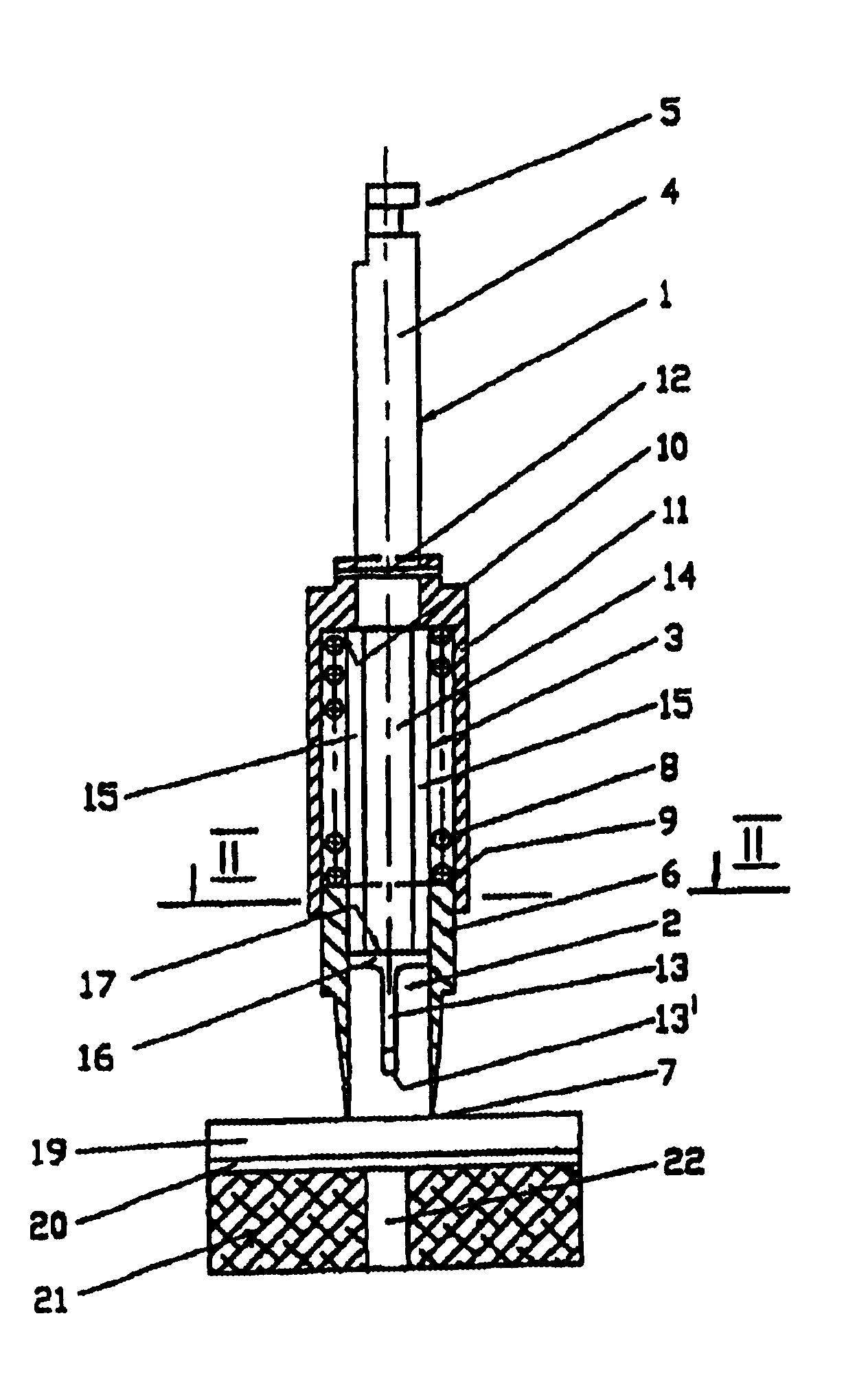
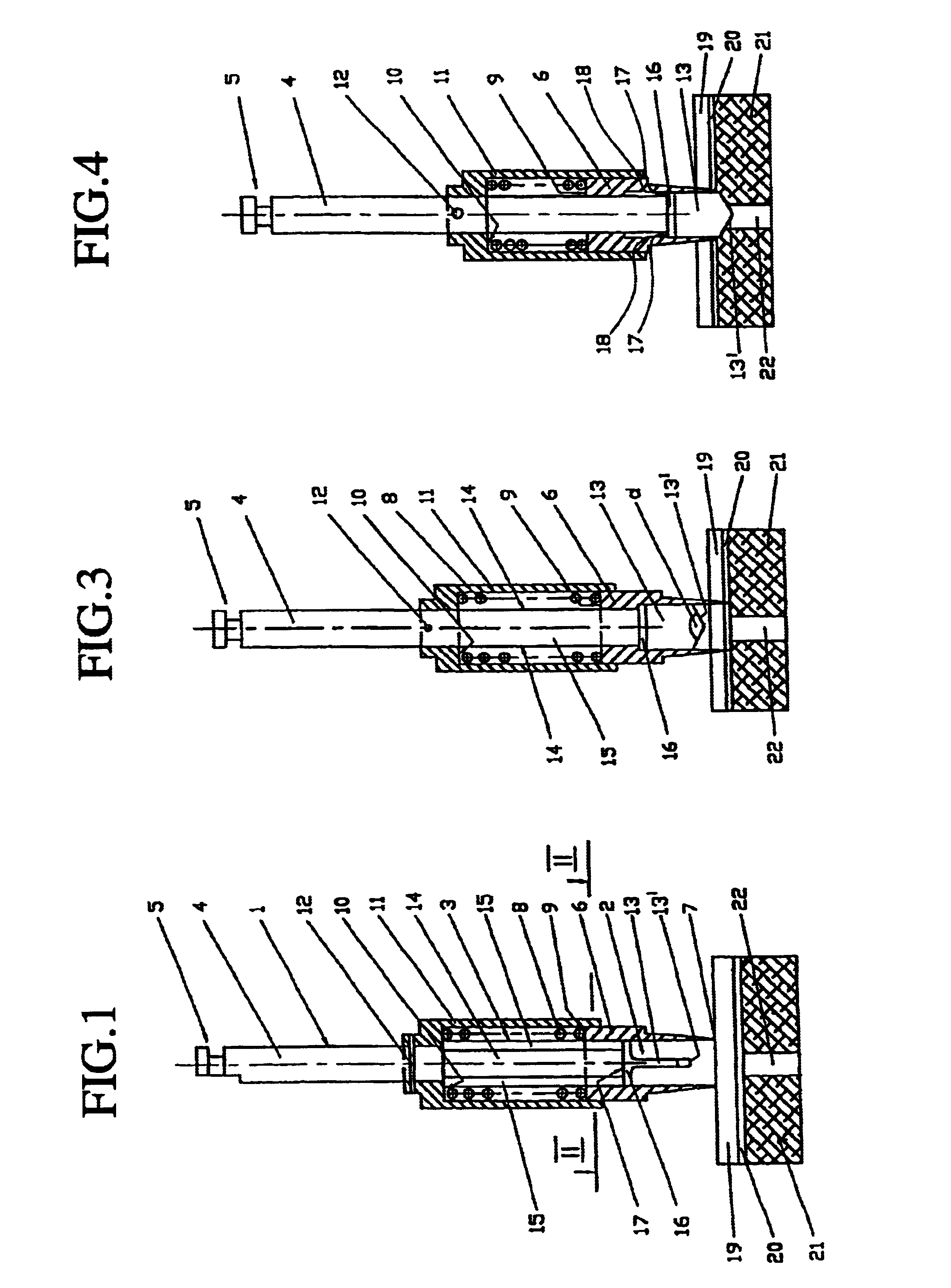
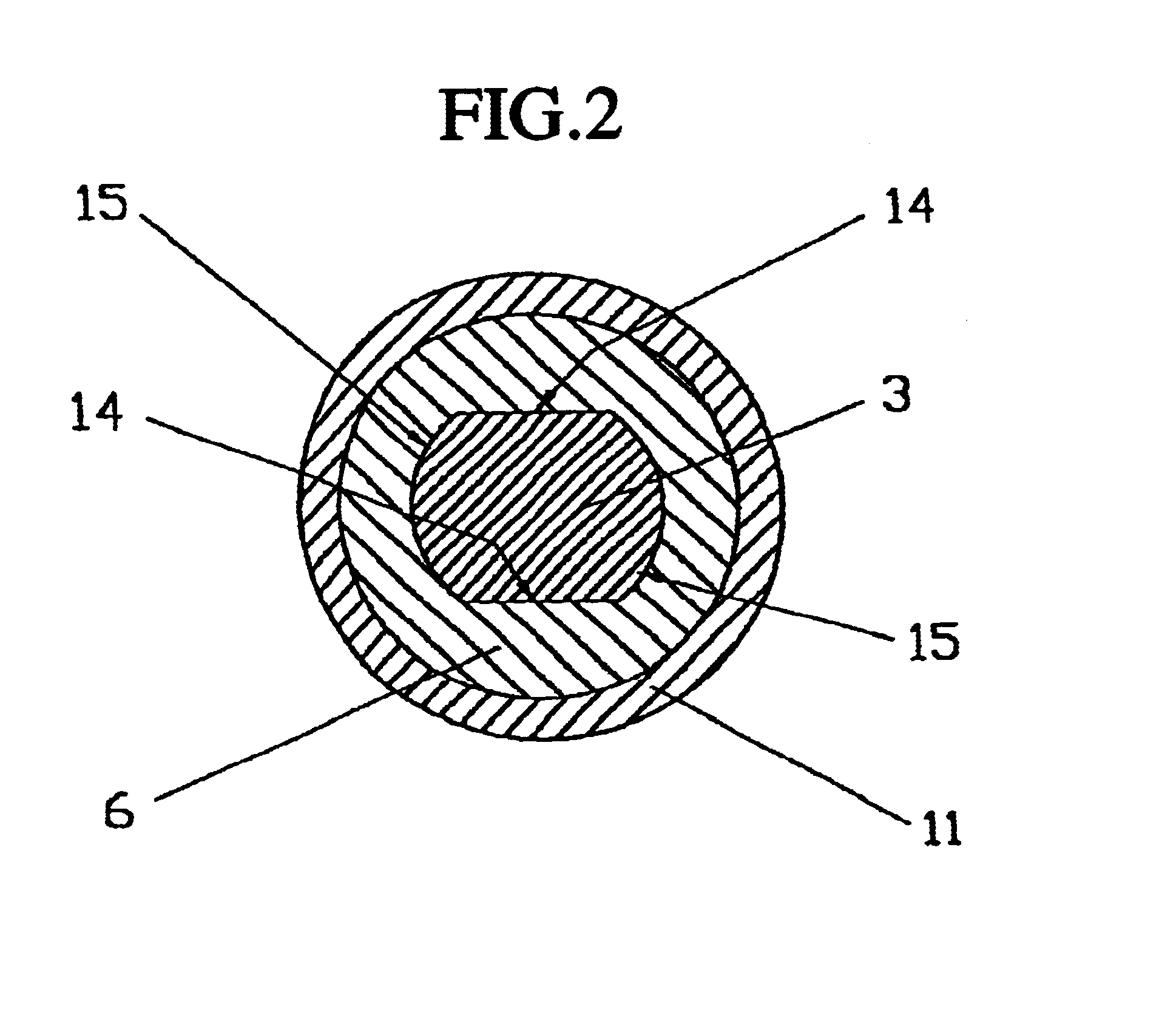
[0012]A milling cutter identified with 1, which is comprised by a milling head 2, a shaft element with a non-circular cross section 3, and a shaft element connecting to the same with a round cross section 4, wherein at the free end of the shaft element projecting upward is provided the extension coupling for applying the handpiece or angle piece.

[0013]The milling cutter 1 is enclosed in the lower region, and in particular in the region of its milling head 2, and in part also in the region of the shaft element with a non-circular cross section 3, by a bushing 6 whose inner cross section corresponds to the outer cross section of shaft element 3 with a non-circular cross section. This bushing has a face 7 at its free end, which is configured as a circular knife edge, and wherewith the bushing forms a rotating stamp. On the area of the bushing facing away from the face 7 of the same is provided a spring 8 enclosing the shaft area 3, whose one end is braced on an inner face 10 of a cylin...


PUM


Abstract

Device provided with a bone milling cutter for application on medical, especially dental handpieces. The milling cutter having a milling head is mounted so as to be displaceable in a bushing which is coupled rotation-locking with the milling cutter in the direction of its axis of rotation. A circular knife edge is provided on the face of the bushing, so that the bushing forms a rotating punch, and the milling head can be pushed out of the plane of the face of the bushing.

Description

BACKGROUND OF THE INVENTION[0001]The invention relates to a device with a bone milling cutter for applying medical, especially dental handpieces, for example angle pieces.[0002]It has been usual until now when setting the dental implant to separate the mucosa surgically from the jaw bone and to split the periosteum. Thereafter, the implant is inserted into the bone according to manufacturer's directions. The surgical wound is subsequently closed by placing several stitches. Such a procedure has the disadvantage that the mucosa, that is, the gingiva, is traumatically penetrated so that the patient can also suffer from pain in the wound for a long time after the work has been concluded.SUMMARY OF THE INVENTION[0003]The object of the invention is to obtain the most atraumatic penetration of the gingiva and the periosteum possible, whereby additionally a circular, conical plateau is to be created in the region of the alveolar crest of the upper jaw or the lower jaw.[0004]This objective ...

Claims


Application Information

Patent Timeline
Patent Type & Authority Patents(United States)
IPC IPC(8): A61B17/16A61C8/00A61C1/08A61C3/02A61C1/12
CPCA61B17/1637A61C8/0089A61C1/084B60W2540/10B60W2540/18
Inventor JESCH, WOLFGANG
Owner DEGUDENT
Why Eureka
Try Eureka