Method for forming scribed groove and scribing apparatus

Inactive Publication Date: 2005-07-12
SUMITOMO ELECTRIC IND LTD
View PDF7 Cites 5 Cited by
  • Summary
  • Abstract
  • Description
  • Claims
  • Application Information

AI Technical Summary

Benefits of technology

[0007]A principal object of the present invention is to offer a method for forming a scribed groove that can reduce the amount of dimensional deviation between the scribed groove and the cleaved plane and that can produc

Problems solved by technology

However, the foregoing conventional groove-forming method has a drawback of a large amount of dimensional deviation between the scribed groove and the cleaved plane. FIG. 14 is a plan view showing a bar-shaped wafer which is cleaved after scribed grooves are formed by the conventional method.
As a result, the large deviation in the outside dimensions makes it difficult to prod

Method used


Image

  • Method for forming scribed groove and scribing apparatus
  • Method for forming scribed groove and scribing apparatus
  • Method for forming scribed groove and scribing apparatus

Examples


Example

[0054]Embodiments of the present invention are explained below by referring to the accompanying drawings. In the drawings, the same number or sign refers to the same element or dimension to avoid duplicated explanation. The ratios of the dimensions in the drawings do not necessarily coincide with the explanation.

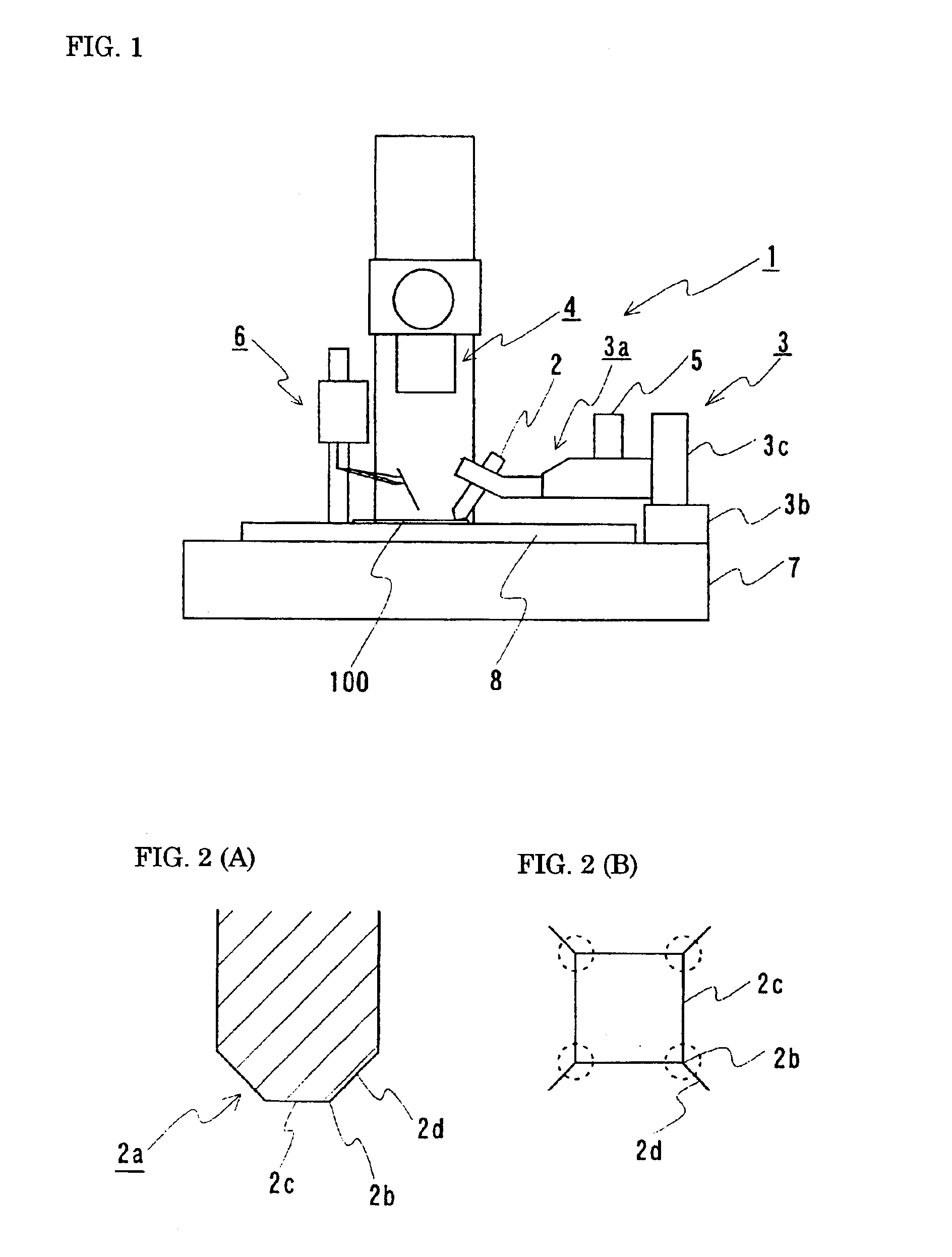
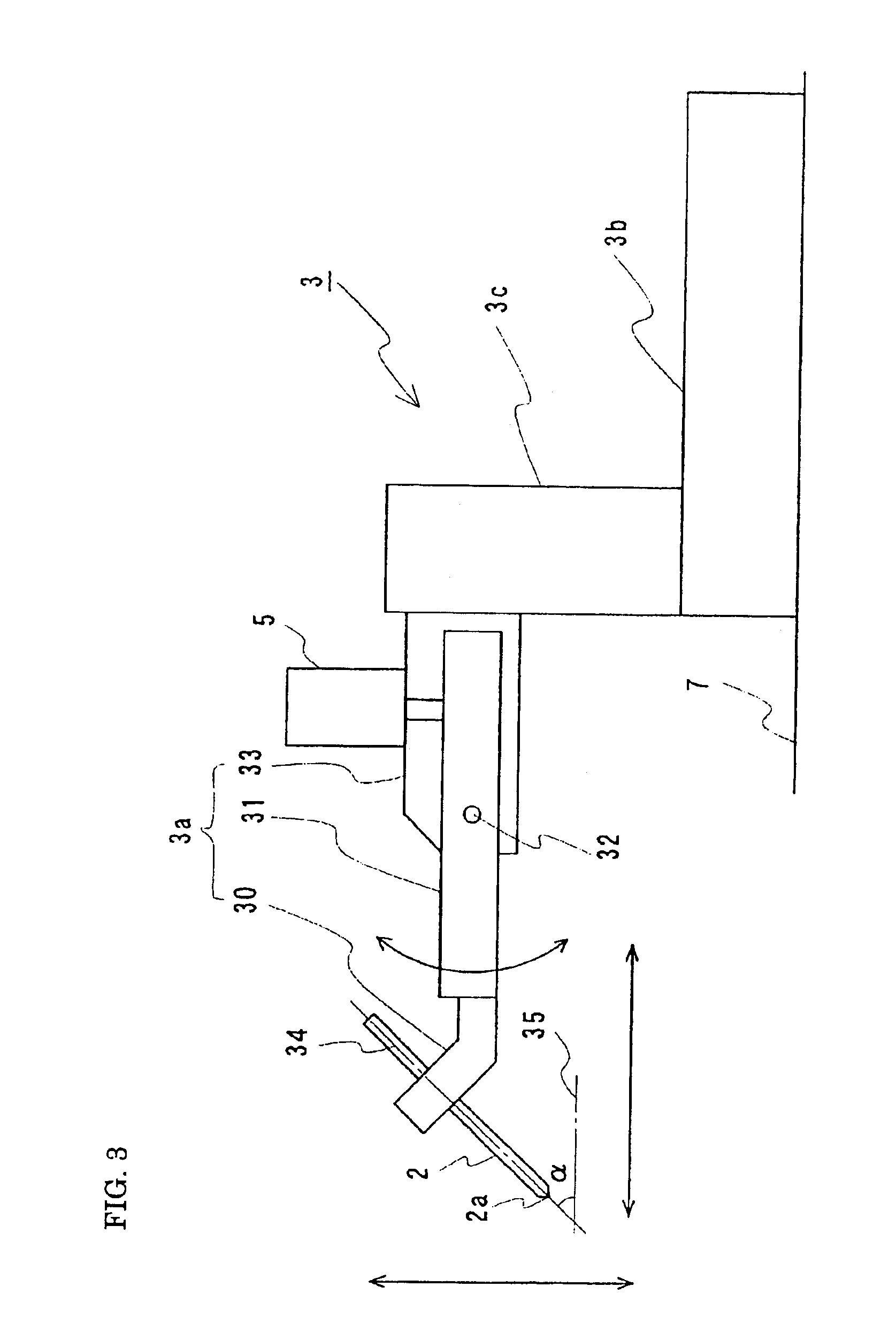
[0055]FIG. 1 is a schematic diagram showing the scribing apparatus of the present invention. FIG. 2(A) is a vertical cross section of the cutting edge of a cutting part. FIG. 2(B) is an enlarged diagram showing the tip portion of the cutting edge. FIG. 3 is a schematic diagram showing a supporting-and-operating portion for the cutting part. FIG. 4 is a diagram illustrating an image pickup portion. FIG. 5 is a schematic diagram showing a thickness-measuring portion. A scribing apparatus 1 of the present invention comprises (a) a cutting part 2 that forms scribed grooves at the surface portion of a wafer 100, (b) a supporting-and-operating portion 3 that supports and moves the...


PUM


Abstract

A method for forming scribed grooves on a wafer and an apparatus for implementing the method. The method moves the cutting part such that its cutting edge forms an inverted trapezoid-shaped path, thereby reducing the scribing angle of the cutting edge to an acute angle. Consequently, the stress produced by the mechanical shock at the time of the scribing can be dispersed in the moving direction of the cutting edge and in a direction perpendicular to the surface of the wafer. The horizontal movement of the scribing cutting edge in the wafer enables the application of a sufficient load in a direction perpendicular to the scribing plane in the wafer. Consequently, vertical cracks are sufficiently generated, and the amount of dimensional deviation between the scribed groove and the cleaved plane is reduced. This method can produce chips featuring outside dimensions with higher precision and cleaved surfaces with high-quality mirror finish.

Description

BACKGROUND OF THE INVENTION[0001]1. Field of the Invention[0002]The present invention relates to a method for forming a scribed groove at the surface portion of a wafer so that the groove can act as the starting point for splitting the wafer to obtain chips by exploiting the cleaving property of the wafer and a scribing apparatus for implementing the method. The present invention particularly relates to a method for forming a scribed groove that can considerably reduce the amount of dimensional deviation between the scribed groove and the cleaved plane and a scribing apparatus for implementing the method.[0003]2. Description of the Background Art[0004]Semiconductor chips are produced by separating them from a wafer such as a laser diode wafer. In this case, scribed grooves are first formed at the surface portion of the wafer with a scribing apparatus. Then, a cleaving prism performs the cleaving work by concentrating the stress on the scribed groove. This is a well known technique. ...

Claims


Application Information

Patent Timeline
IPC IPC(8): H01L21/02H01L21/304H01L21/70H01L21/78C03B33/037H01L21/301C03B33/023
CPCH01L21/3043H01L21/78
Inventor OHNO, YUJIIMAI, HIROSHINAKASE, YOSHITO
Owner SUMITOMO ELECTRIC IND LTD
Why Eureka
Try Eureka