Motion guide apparatus and method for manufacturing the same

a technology of motion guide apparatus and assembly method, which is applied in the direction of linear bearings, shafts and bearings, bearings, etc., can solve the problems of time and trouble, and achieve the effects of facilitating the operation of assembling the circulation path, reducing the influence of a dimensional deviation of each component, and facilitating the assembly of the motion guide apparatus and sliding performan

Active Publication Date: 2018-01-09
THK CO LTD
View PDF27 Cites 4 Cited by
  • Summary
  • Abstract
  • Description
  • Claims
  • Application Information

AI Technical Summary

Benefits of technology

[0010]According to the first aspect of the present invention, the pair of the end members is molded integrally with both ends of the holding portion, and the component is incorporated into the moving member body in the direction orthogonal to the movement direction of the moving member body. Accordingly, the positions of the pair of the end members can be determined in the movement direction of the moving member body, and an operation of assembling the circulation path is facilitated.
[0011]According to the second aspect of the present invention, the positions of the moving member body, the lid member, and the end member can be collectively determined at the position of the boss of the lid member. Accordingly, the influence of a dimensional deviation of each component can be reduced, and ease of assembly of the motion guide apparatus and sliding performance (that is, the smooth movement of the rolling elements) are improved.

Problems solved by technology

However, the rolling element loading operation is an operation in a small space; therefore, there is a problem that it takes time and trouble.

Method used


Image

  • Motion guide apparatus and method for manufacturing the same
  • Motion guide apparatus and method for manufacturing the same
  • Motion guide apparatus and method for manufacturing the same

Examples


second embodiment

[0059]The motion guide apparatus according to the present invention has the following effects. The first to third holding portions 55-1 to 55-3 are formed integrally with the resin component 56. Accordingly, the resin component 56 can hold the balls 42 alone, and can resist to torsion. Furthermore, the necessity to process the holding portion carrying the balls 42 in the moving block body 53 is eliminated. Accordingly, the shape of the inner side of the sleeve portion 53-2 of the moving block body 53 can be simplified. Furthermore, the resin component 56 is divided into two: the left and right parts. Accordingly, even if the lower ends of the pair of left and right sleeve portions 53-2 of the moving block body 53 extend inward, the resin component 56 can be incorporated into the moving block body 53.

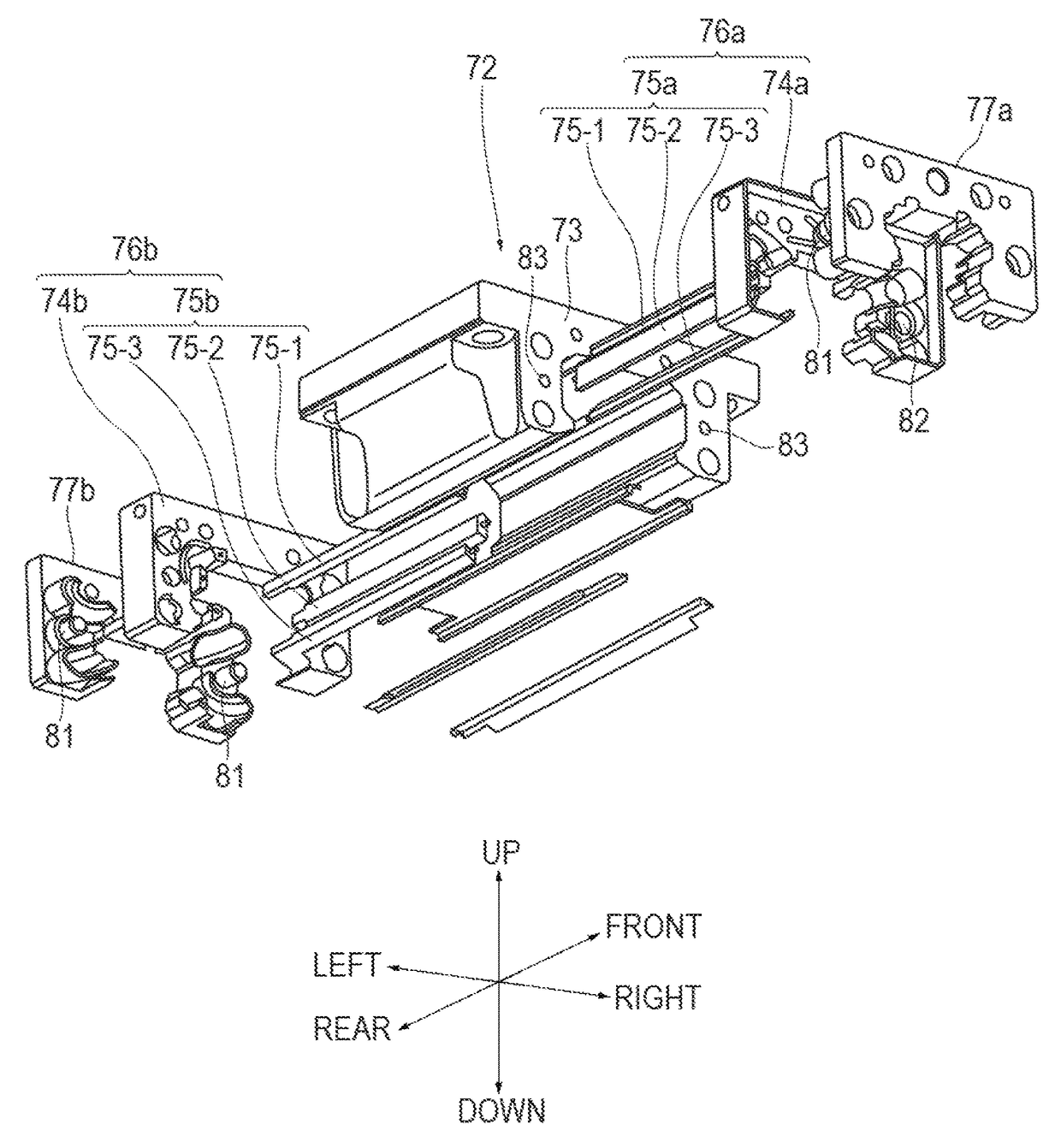
[0060]FIG. 14 illustrates an exploded perspective view of a moving block 72 according to a third embodiment of the present invention. The moving block 72 according to the third embodimen...

third embodiment

[0063]In the moving block 72 upon the assembly of the moving block 72, firstly the resin components 76a and 76b are incorporated from the front and the rear of the moving block body 73 toward a movement direction of the moving block body 73. After the resin components 76a and 76b are incorporated into the moving block body 73, distal ends of the holding portion 75a of the resin component 76a are fitted in the end plate 74b of the resin component 76b. Distal ends of the holding portion 75b of the resin component 76b are fitted in the end plate 74a of the resin component 76a. The fitting of the lid members 77a and 77b in the end plates 74a and 74b enables the determination of the positions of the moving block body 73, the resin components 76a and 76b, and the lid members 77a and 77b.

[0064]The present invention is not limited to concretization in the above embodiments. The present invention can be concretized in various embodiments within the scope that does not change the gist of th...

first embodiment

[0065]In the above first embodiment, after the lid member and the end plate are fixed to the moving block body with the screws, the balls are loaded into the circulation paths. However, it is also possible to load the balls into the circulation paths in the stage where the lid member and the end plate are temporarily fixed to the moving block body before being fixed with the screws.

[0066]In the above first embodiment, the end plate is not divided into a left and a right part. However, the end plate can also be divided into a left and a right part along a cross section in the longitudinal direction of the track rail.

[0067]In the above first to third embodiments, the bosses provided to the lid members are used as the positioning means. However, bosses separated from the lid members can also be used.

[0068]In the above first to third embodiments, the return path of the circulation path comprises the through hole in the moving block body. However, the return path can also comprise a resi...


PUM

PropertyMeasurementUnit
movementaaaaaaaaaa
timeaaaaaaaaaa
widthaaaaaaaaaa

Abstract

An object is to provide a motion guide apparatus that can facilitate an assembly operation. An end member (4a, 4b) including an inner peripheral side of a direction changing path (2c) is placed on an end surface in a movement direction of a moving member body (3). At least one of a pair of the end members (4a and 4b) includes an opening (21) linking to the inner peripheral side of the direction changing path (2c) to load rolling elements (42) into a circulation path. Opposing surfaces (18) of the pair of the end members (4a and 4b) to the moving member body (3) are formed in flat surfaces. The pair of the end members (4a and 4b) molded integrally with a holding portion (5) is incorporated into the moving member body (3) in a direction orthogonal to the movement direction of the moving member body (3). A lid member (7a, 7b) closes the opening (21) in the end member (4a, 4b).

Description

TECHNICAL FIELD[0001]The present invention relates to a motion guide apparatus including a track member and a moving member assembled in a movable manner to the track member via rolling elements, and a method for manufacturing the motion guide apparatus.BACKGROUND ART[0002]A motion guide apparatus that guides the linear motion of a mobile body such as a table using the rolling motion of rolling elements is known. The motion guide apparatus is also called a linear guide, and includes a track rail, and a moving block assembled in a movable manner to the track rail via rolling elements. A rolling element rolling portion where the rolling elements can make a rolling motion is formed along a longitudinal direction in the track rail. A circulation path for circulating the rolling elements is formed in the moving member. The circulation path includes a loaded rolling element rolling portion facing the rolling element rolling portion of the track rail, a return path parallel to the loaded r...

Claims


Application Information

Patent Timeline
Patent Type & Authority Patents(United States)
IPC IPC(8): F16C29/06F16C43/04
CPCF16C29/0607F16C43/04F16C29/0647F16C29/0609F16C2220/02F16C29/0602F16C29/0645
Inventor TOMITA, SHIGEOSAKAI, JUNICHIMAKI, NOBUYUKIHOSHIDE, KAORUYAMAMURA, KATSUNORIIWAMOTO, MUTENHORIIKE, KAZUYANARATA, KENJINAKANO, FUKUJINAKAMURA, SHIGEMIIRIE, YOSUKENAKAMURA, YUKI
Owner THK CO LTD
Why Eureka
Try Eureka