
Jointing holder for optical module for single-fiber bidirectional communication and optical module incorporating the jointing holder

a single-fiber bidirectional communication and optical module technology, applied in the direction of optical elements, electromagnetic transceivers, instruments, etc., can solve the problems of significant cost increase, difficult miniaturization of modules, and difficulty in positioning fixing members to enclosures, so as to reduce dimensional deviation

Active Publication Date: 2005-02-03
SUMITOMO ELECTRIC IND LTD
View PDF15 Cites 1 Cited by
  • Summary
  • Abstract
  • Description
  • Claims
  • Application Information

AI Technical Summary

Benefits of technology

The present invention offers a jointing holder for an optical module that can be used for single-fiber bidirectional communication. The holder has several advantages over other fixing members, including a smaller size, reduced cost, and improved assembly precision. The holder includes an optical fiber-fixing portion, a semiconductor laser-fixing portion, a photodiode-fixing portion, an optical path-forming space, and an optical filter-fixing face. The holder can be used with an optical module that includes an optical fiber, a semiconductor laser, a photodiode, and an optical filter for separating multiplexed wavelengths. The jointing holder simplifies the adjustment of the optical axes of the components and reduces the dimensional deviation during assembly. The optical module using the jointing holder is small, cost-effective, and easy to assemble with high precision.

Problems solved by technology

This structure has the following drawbacks: (a) A large number of components make it difficult to miniaturize the module.
(b) The positioning of the fixing members to the enclosure is difficult.
(d) An intention to increase the precision leads to a significant increase in the cost.

Method used


Image

  • Jointing holder for optical module for single-fiber bidirectional communication and optical module incorporating the jointing holder
  • Jointing holder for optical module for single-fiber bidirectional communication and optical module incorporating the jointing holder
  • Jointing holder for optical module for single-fiber bidirectional communication and optical module incorporating the jointing holder

Examples


Embodiment Construction

[0029] Embodiments of the present invention are explained below by referring to the accompanying drawings. To avoid duplicated explanations, the same signs are allocated to the same members throughout the drawings.

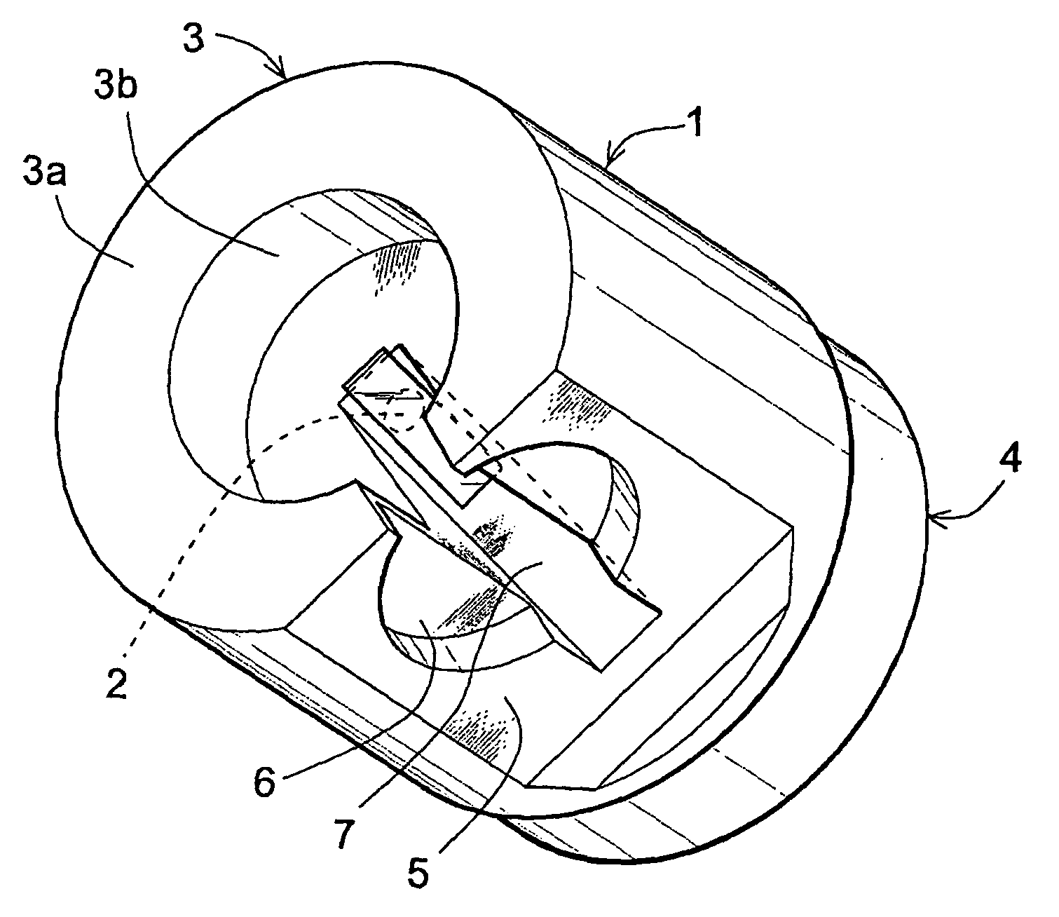
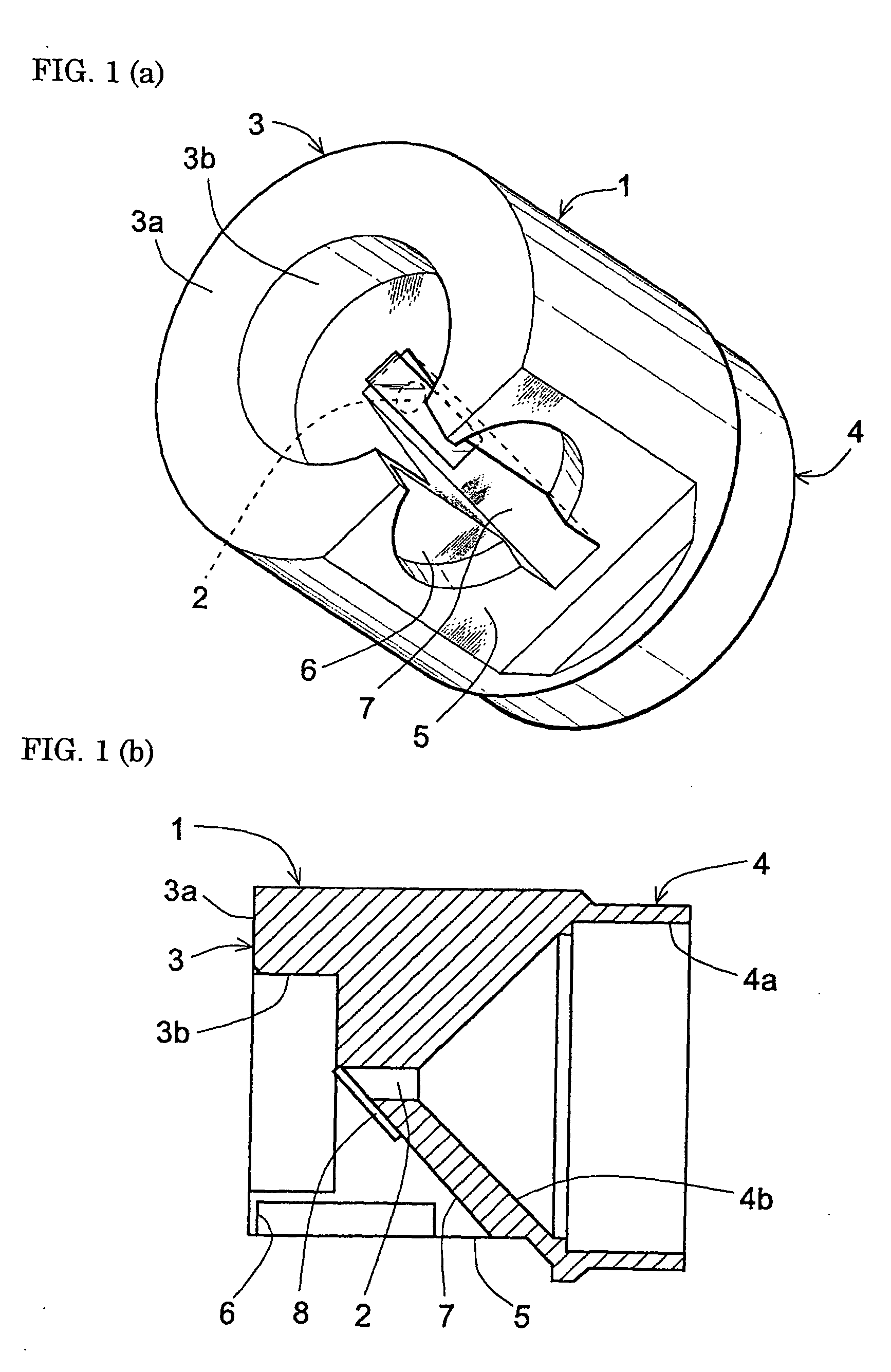
[0030] FIGS. 1(a) and 1(b) show the first embodiment of the jointing holder of the present invention. The jointing holder comprises a cylindrical body 1 having a basically cylindrical form produced by machining a material made of stainless steel with a lathe. The cylindrical body 1 has an optical path-forming hole 2 at the axis of the cylindrical form. The cylindrical body 1 has an optical fiber-fixing portion 3 at one end and a semiconductor laser-fixing portion 4 at the other end. The optical fiber-fixing portion 3 has a ferrule holder-fixing face 3a perpendicular to the axis of the cylindrical form and an optical fiber ferrule-storing hole 3b.

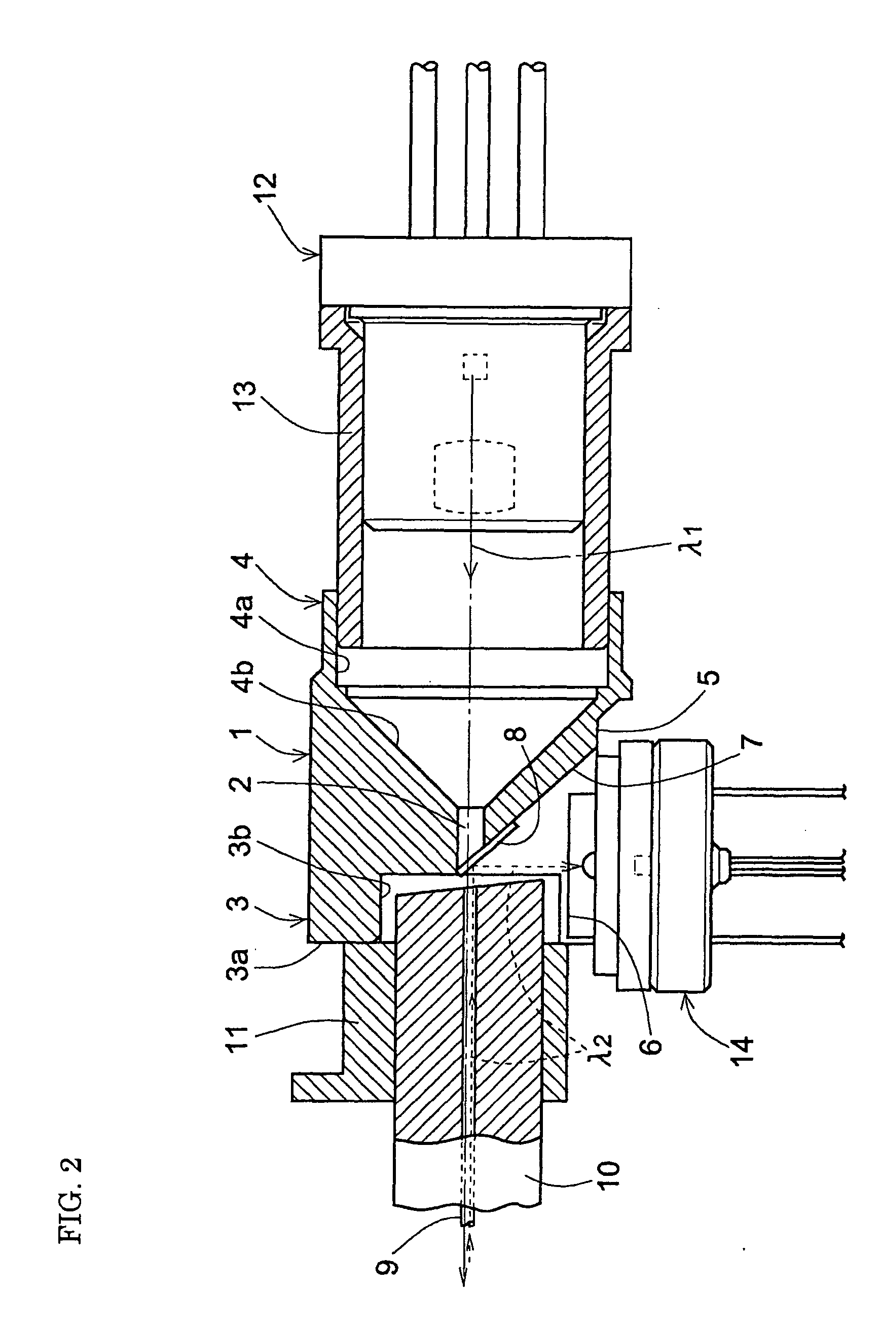
[0031]FIG. 2 is a longitudinal cross section of an optical module for single-fiber bidirectional communication assembled by usi...


PUM


Abstract

A jointing holder for an optical module for single-fiber bidirectional communication comprises a unitarily structured cylindrical body that has the following portions: (a) an optical fiber-fixing portion for securely holding an optical fiber for transmitting multiwavelength light bidirectionally, (b) a semiconductor laser-fixing portion for securely holding a semiconductor laser for emitting outgoing light λ 1, (c) a photodiode-fixing portion for securely holding a photodiode for receiving incoming light λ 2, (d) an optical path-forming space for optically coupling the optical fiber, the semiconductor laser, and the photodiode, and (e) in the optical path-forming space, an optical filter-fixing face for securely holding an optical filter for separating multiplexed wavelengths. The jointing holder enables the optical module to reduce the number of components, to be miniaturized, and to reduce the dimensional deviation at the time of the assembly, enabling high-precision assembly. An optical module for single-fiber bidirectional communication incorporates the jointing holder.

Description

BACKGROUND OF THE INVENTION [0001] 1. Field of the Invention [0002] The present invention relates to a jointing holder for an optical module for single-fiber bidirectional communication for securely holding an optical fiber for transmitting multiwavelength light bidirectionally, a semiconductor laser for emitting outgoing light, a photodiode for receiving incoming light, and an optical filter for separating multiplexed wavelengths. The present invention also relates to an optical module for single-fiber bidirectional communication incorporating the jointing holder. [0003] 2. Description of the Background Art [0004] In the subscriber loop represented by the FTTH (fiber to the home) system in an optical fiber communications system, signal transmission and reception is mainly performed by a wavelength division multiplexing system using two wavelengths in a 1.3-μm band and a 1.55-μm band transmitted over a single optical fiber. For such a wavelength division multiplexing system, Europea...

Claims


Application Information

Patent Timeline
Patent Type & Authority Applications(United States)
IPC IPC(8): G02B6/38G02B6/42
CPCG02B6/3818G02B6/4214H04B10/40G02B6/4292G02B6/4246
Inventor OKADA, TAKESHIKUHARA, YOSHIKINAKANISHI, HIROMI
Owner SUMITOMO ELECTRIC IND LTD
Learn More