

Heat transfer material having meltable layers separated by a release coating layer
a technology of heat transfer material and release coating layer, which is applied in the direction of weaving, transportation and packaging, synthetic resin layered products, etc., can solve the problems of fading of the transfer image-bearing coating, poor appearance, and less than desirable finished products, and achieve the effect of improving the breathability of the coated substra
- Summary
- Abstract
- Description
- Claims
- Application Information
AI Technical Summary
Benefits of technology
Problems solved by technology
Method used
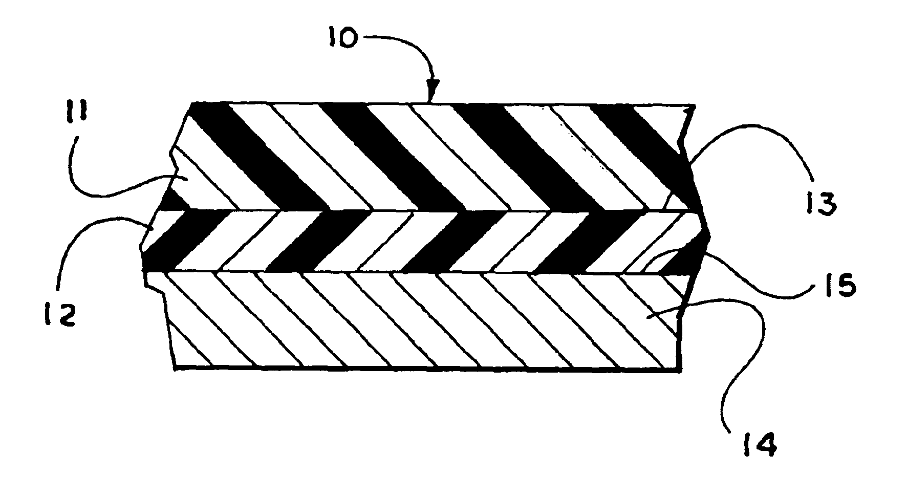
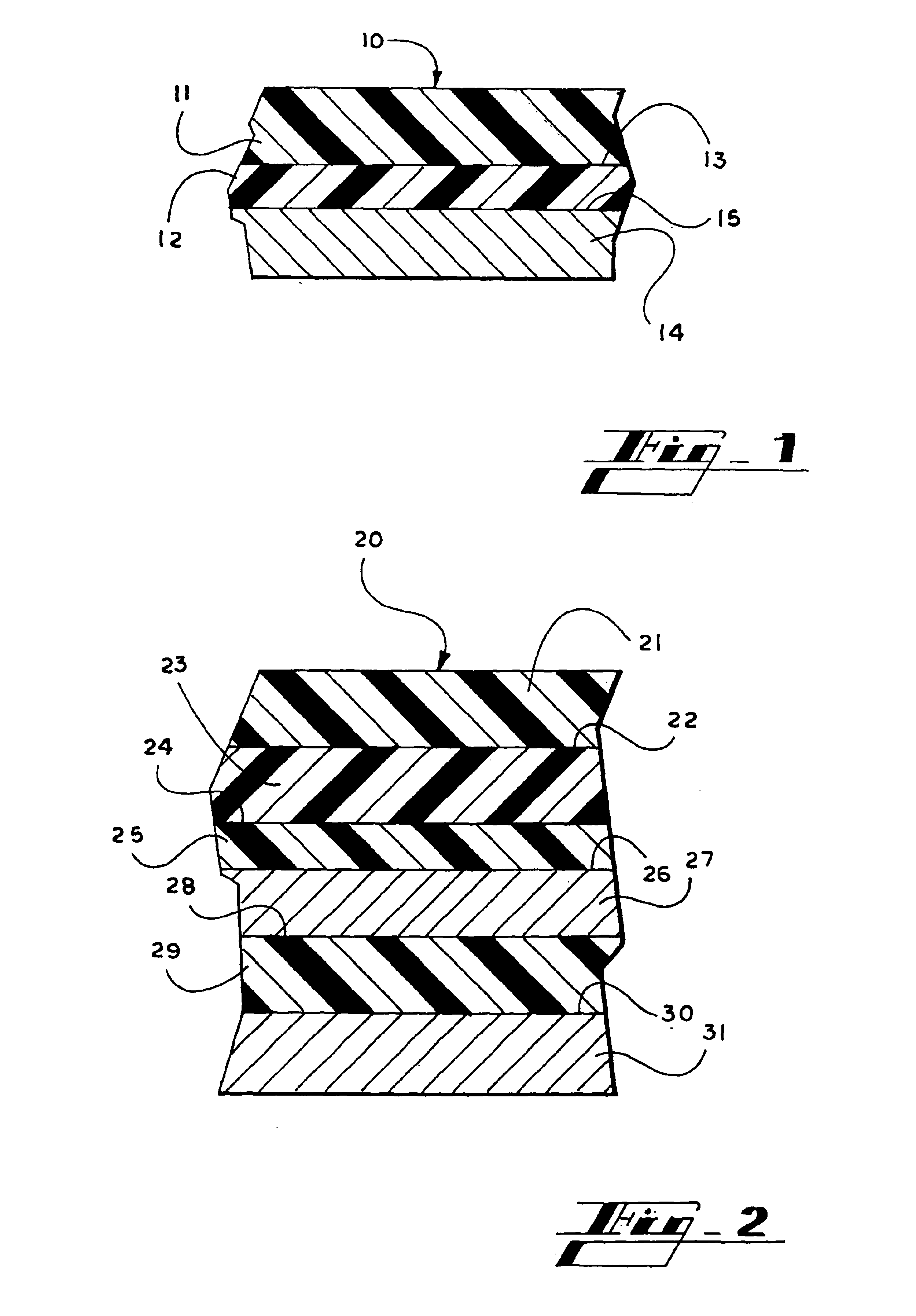
Image

Examples
example 1
Preparation of Heat Transfer Materials Having a Thermal Ribbon Printed Image Thereon
[0235]Heat transfer materials were prepared from the above-described layers. The components of the heat transfer materials are shown below in Table 1. Images were printed onto the heat transfer materials using a thermal ribbon printer.
[0236]
TABLE 1Thermal Ribbon Printable DesignsBaseBaseReleaseSample #PaperCoatCoatPrint CoatTR1BP3BC1RC1PCT1TR2BP3BC1RC2PCT2TR3BP3BC1RC2PCT4TR4BP3BC1RC3PCT4TR5BP3BC1RC4PCT4TR6BP3BC1RC5PCT4TR7BP3BC1RC5LCP5TR8BP1BC2RC6LCP5TR9BP1BC2RC6LCP6TR10BP1BC2RC6PCT4TR11BP1BC2RC13PCT2TR12BP1BC2RC14PCT4TR13BP1BC2RC14PCT9TR14BP1BC2RC15PCT6TR15BP1BC2RC16PCT9TR16*BP3BC1NONEPCT1*Comparative example having no release coat.
Comparative example having no release coat.
[0237]For good thermal ribbon printing results, smoothness of the base substrate is known to be a desirable factor. Better printing results are obtained when there is good contact between the heat transfer sheet and the ribbon. F...
example 2
Preparation of Heat Transfer Materials Having a Laser Color Copier Printed Image Thereon
[0240]Heat transfer materials were prepared from the above-described layers using the procedure outlined in Example 1. The components of the heat transfer materials are shown below in Table 2. Images were copied onto the heat transfer materials using a Canon 700 laser color copier.
[0241]
TABLE 2Color Laser Copier DesignsBaseBaseReleasePrintSamplePaperCoatCoatCoatCLC1BP1BC2RC5PCT4CLC2BP1BC2RC5LCP5CLC3BP1BC2RC5LCP6CLC4BP1BC2RC14PCT8CLC5BP1BC2RC14PCT9CLC6BP1BC2RC14LCP3CLC7BP1BC2RC16PCT9CLC8*BP1BC2CLC9**BP6RC10BC1*Comparative example using hot removal of paper, having a single layer of meltable coating. **Comparative example using cold removal of paper, having a release coat and an outside single layer of meltable coating.
[0242]Bond papers such as BP1 and BP6 in the tables above worked well for photocopier grades, due to their stiffness, conductivity, caliper, and smoothness required for photocopying...
example 3
Preparation of Heat Transfer Materials Having an Ink Jet Printed Image Thereon
[0246]Heat transfer materials were prepared from the above-described layers using the procedure outlined in Example 1. The components of the heat transfer materials are shown below in Table 3. Images were printed onto the heat transfer materials using an ink jet printer;
[0247]
TABLE 3Ink Jet Printable DesignsBaseBaseReleaseSub-PrintTopSamplePaperCoatCoatCoatCoatCoatIJ1BP3BC1RC6SC1PIJ1NONEIJ2BP3BC1RC6LCP5PIJ1NONE(SC2)IJ3BP3BC1RC6LCP6PIJ1NONE(SC3)IJ4BP2BC3RC6SC4PIJ1NONEIJ5BP2BC3RC6SC5PIJ1NONEIJ6BP2BC1RC10NONEPIJ2TC1IJ7BP1BC2RC11NONEPIJ2TC1IJ8BP1BC2RC11SC6PIJ2TC1IJ9BP1BC2RC11SC7PIJ2TC1(PCT8)IJ10BP1BC2RC11SC8PIJ2TC1IJ11BP1BC2RC11SC9PIJ2TC1IJ12BP1BC2RC11NONEPIJ2NONEIJ13BP1BC2RC11NONEPIJ3TC1IJ14BP1BC2RC12NONEPIJ2NONEIJ15BP1BC2RC12NONEPIJ2TC1IJ16BP1BC2RC12PCT8PIJ2NONEIJ17BP1BC2RC12PCT8PIJ2TC1IJ18BP1BC2RC12NONEPIJ5NONEIJ19BP1BC2RC12NONEPIJ6NONEIJ20BP1BC2RC10NONEPIJ6NONEIJ21BP1BC2RC10NONEPIJ9NONEIJ22BP1BC2RC10NONEPI...
PUM
| Property | Measurement | Unit |
|---|---|---|
| softening temperature | aaaaa | aaaaa |
| softening temperature | aaaaa | aaaaa |
| softening temperature | aaaaa | aaaaa |
Abstract
Description
Claims
Application Information