Vehicular lamp

Inactive Publication Date: 2005-07-12
KOITO MFG CO LTD
View PDF4 Cites 9 Cited by
  • Summary
  • Abstract
  • Description
  • Claims
  • Application Information

AI Technical Summary

Benefits of technology

[0012]The impedance changing unit may include: a switch connected in parallel to the light source; and a resistor, connected in parallel to the light source and in series with the switch, operable to allow a transmission-line current that is a current from one of the two power transmission lines to the other power transmission line in a case where the switch is turned on, and the breaking detection unit may turn the switch on to allow the transmission-line current to flow in the resistor in a case where the breaking detection unit detected the breaking, thereby making the impedance changing unit change the impedance to a smaller value.
[0013]The light source may receive the power that intermits at a predetermined period; the breaking detection unit may detect the breaking during a time period in which the light source receives the power; and the impedance changing unit may further includes a limiting capacitor operable to limit a time in which the impedance is smaller than a predetermined value by changing the transmission-line current during the time period in a case where the breaking detection unit detected the breaking.
[0014]The light source may receive the power that intermits at a predetermined period; the breaking detection unit may detect the breaking during a time period in which the light source receives the power

Problems solved by technology

Thus, according to the conventional technique, the braking of the light source was not detected appropriately in some cases.

Method used


Image

  • Vehicular lamp
  • Vehicular lamp
  • Vehicular lamp

Examples


first embodiment

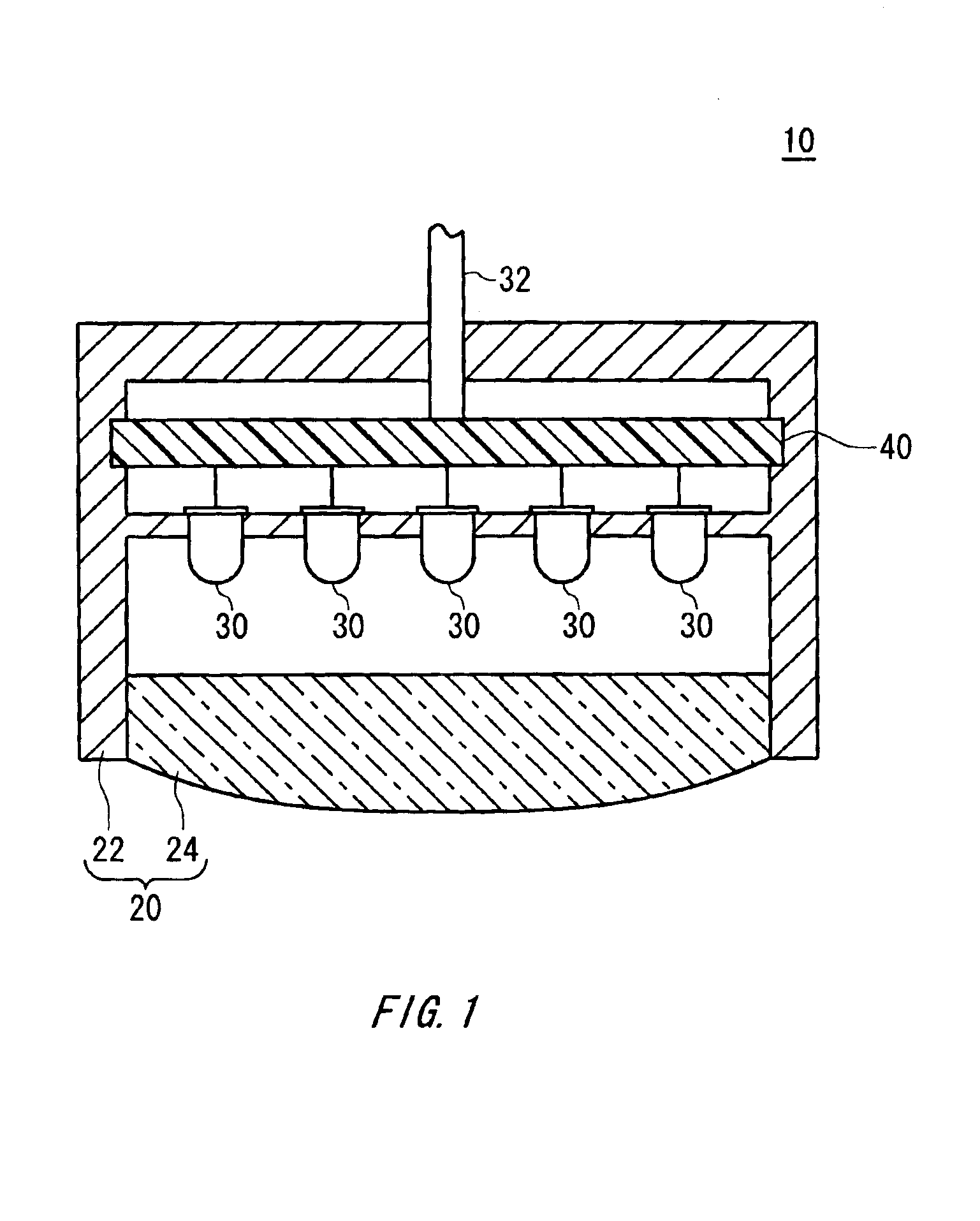
[0039]FIG. 1 shows an example of cross-section of a vehicular lamp 10 according to the present invention. The vehicular lamp 10 is provided in a body of a vehicle such as a car, and used as a stop lamp, taillight, turn signal and the like. The vehicular lamp 10 of the present embodiment notifies to the outside of a lamp body 20 of information indicating breaking of a light source 30.

[0040]The vehicular lamp 10 includes the lamp body 20, a circuit board 40, a plurality of light sources 30 and a wiring 32. The lamp body 20 includes a transmitting part 24 that transmits light generated by the light sources 30 and a holder 22 for accommodating the circuit board 40 and a plurality of light sources 30 therein. The transmitting part 24 may be a lens that can diffuse or converge the light generated by the light sources 30. The lamp body 20 has a function of protecting the light sources 30 and the circuit board 40 from water. That is, the lamp body 20 seals the light sources 30 and the circu...

second embodiment

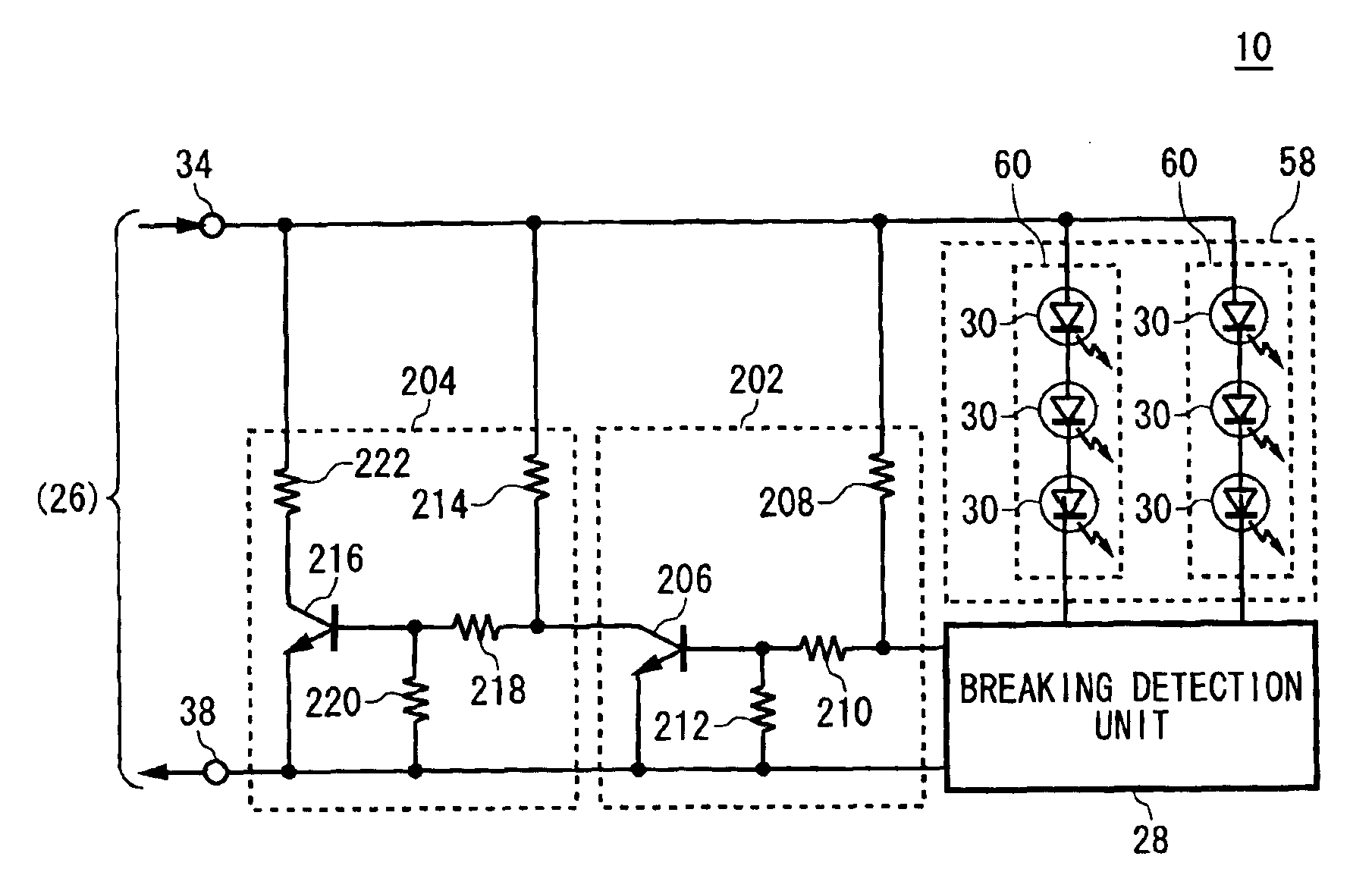
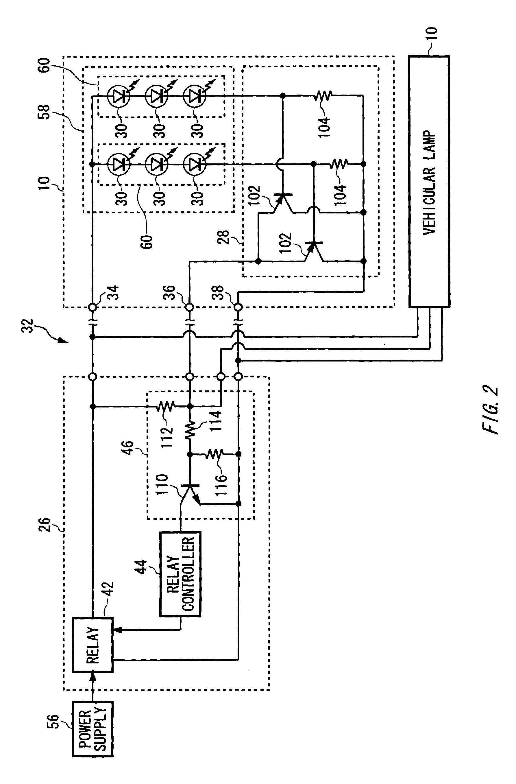
[0064]FIGS. 6A and 6B show an exemplary structure of the vehicular lamp 10 according to the present invention. FIG. 6A shows an exemplary circuit structure of the vehicular lamp 10. The vehicular lamp 10 in this example changes transmission-line impedance that is impedance between two power transmission lines that are electrically connected to terminals 34 and 36, respectively, thereby notifying a flasher-relay unit 26 provided in the outside of a lamp body 20 (see FIG. 1) of information indicating breaking of a light source 30.

[0065]In the present embodiment, the vehicular lamp 10 includes a light source block 58, a breaking detection unit 28, an output transmission unit 202 and an impedance changing unit 204. In FIG. 6, the components labeled with the same reference numerals as those in FIG. 2 have the same or similar functions as / to the components in FIG. 2 and therefore the description thereof is omitted.

[0066]In the present embodiment, the vehicular lamp 10 receives power from ...


PUM


Abstract

A vehicular lamp used in a vehicle, includes: a light source including a light-emitting diode for emitting light in accordance with power received from a power supply provided in the outside of the vehicular lamp; a lamp body for accommodating the light source therein to protect the light source from water; and a breaking detection unit for detecting breaking of the light source and notifying the outside of the lamp body of the detection result.

Description

[0001]This patent application claims priority from a Japanese patent application No. 2002-289288 filed on Oct. 1, 2002, the contents of which are incorporated herein by reference.BACKGROUND OF THE INVENTION[0002]1. Field of the Invention[0003]The present invention relates to a vehicular lamp used in a vehicle.[0004]2. Description of the Related Art[0005]Conventionally, a vehicular lamp that uses a filament bulb as a light source is known. In this type of lamp, breaking of the light source was detected by measuring impedance of the lamp, for example. Moreover, a breaking detection device for an automotive lamp is conventionally known that is used as a multiple light brake light and the like as disclosed, for example, in Japanese Patent Application Laid-Open No. 10-217851, pages 3-4, FIGS. 1-3.[0006]However, in a case where a light-emitting diode is used as the light source, a lighting circuit having large impedance may be used because the light-emitting diode can emit light by a smal...

Claims


Application Information

Patent Timeline
IPC IPC(8): H05B33/02H05B37/00H05B37/03H05B33/08B60Q1/44B60Q11/00B60Q1/00H05B44/00
CPCH05B33/0845H05B33/0893H05B37/032Y02B20/341Y10S362/80H05B45/58H05B47/22H05B45/52Y02B20/30H05B45/10H05B47/21
Inventor ITO, MASAYASUSUGIMORI, SHOGOTAKEDA, HITOSHI
Owner KOITO MFG CO LTD
Why Eureka
Try Eureka