Monitoring and control for power electronic system

a technology of electronic system and monitoring and control, applied in the direction of electrical equipment, ac network circuit arrangements, instruments, etc., can solve the problems of not providing adequate diagnostics or system control, and achieve the effect of optimizing the operation of the power electronic system, increasing the reliability of operation, and efficient achievemen

Inactive Publication Date: 2005-07-12
S&C ELECTRIC
View PDF5 Cites 55 Cited by
  • Summary
  • Abstract
  • Description
  • Claims
  • Application Information

AI Technical Summary

Benefits of technology

[0008]These and other objects of the present invention are efficiently achieved by a control method and arrangement that monitors the condition and operating parameters of a power electronic system having power electronic devices and responds to various detected abnormalities to optimize operation of the power electronic system. The arrangement increases reliability of operation and optimizes the continuous supply of power to a load. The arrangement also includes the capability for diagnosing the parameters of the power electronic switches including drive current, drive voltage and operating temperature and for communicating the status information in a coordinated fashion.

Problems solved by technology

While these arrangements may be useful and generally satisfactory for their intended purposes, they do not provide appropriate diagnostics or system control with sufficient emphasis on the priority of the continuous supply of the connected load.

Method used


Image

  • Monitoring and control for power electronic system
  • Monitoring and control for power electronic system
  • Monitoring and control for power electronic system

Examples


Embodiment Construction

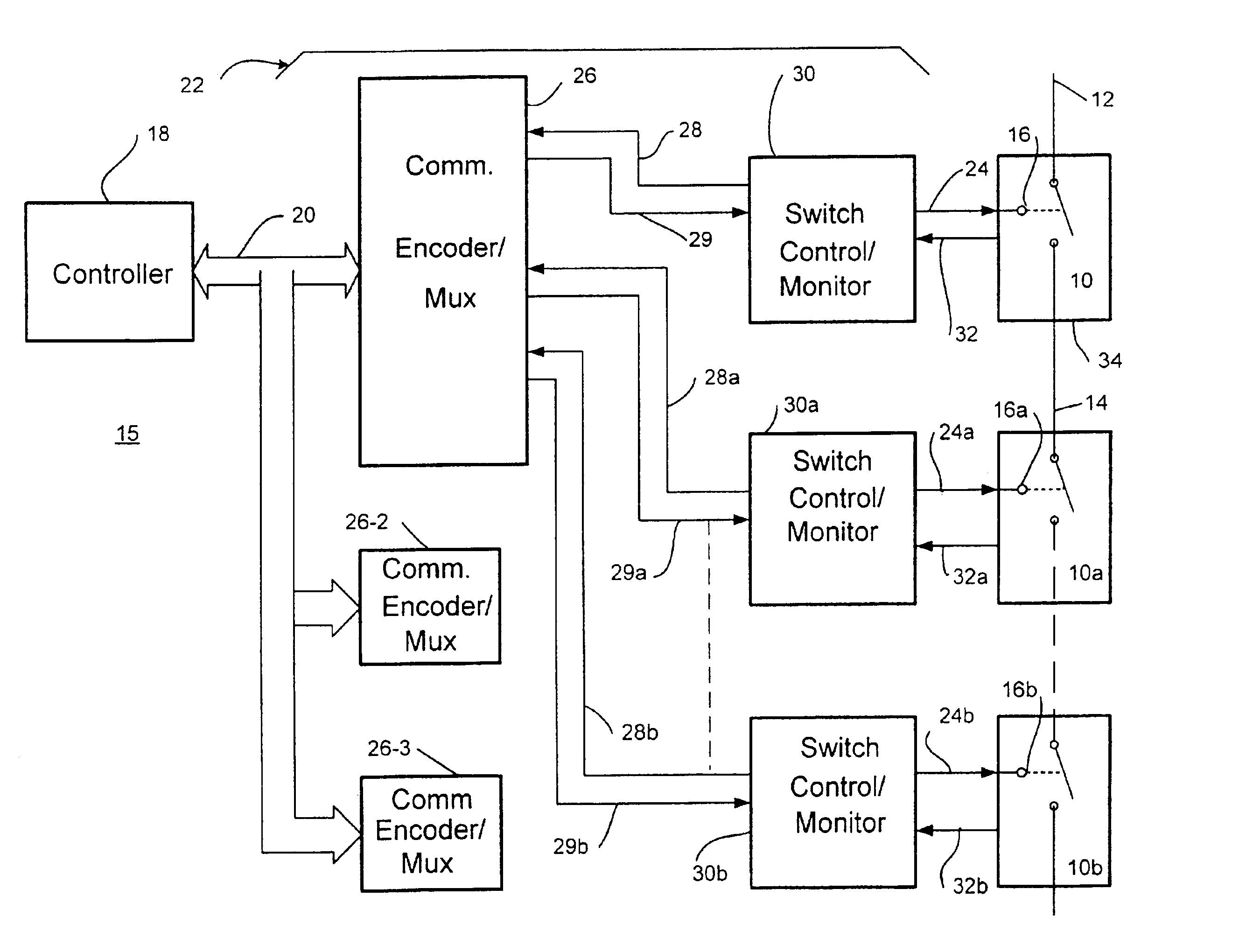
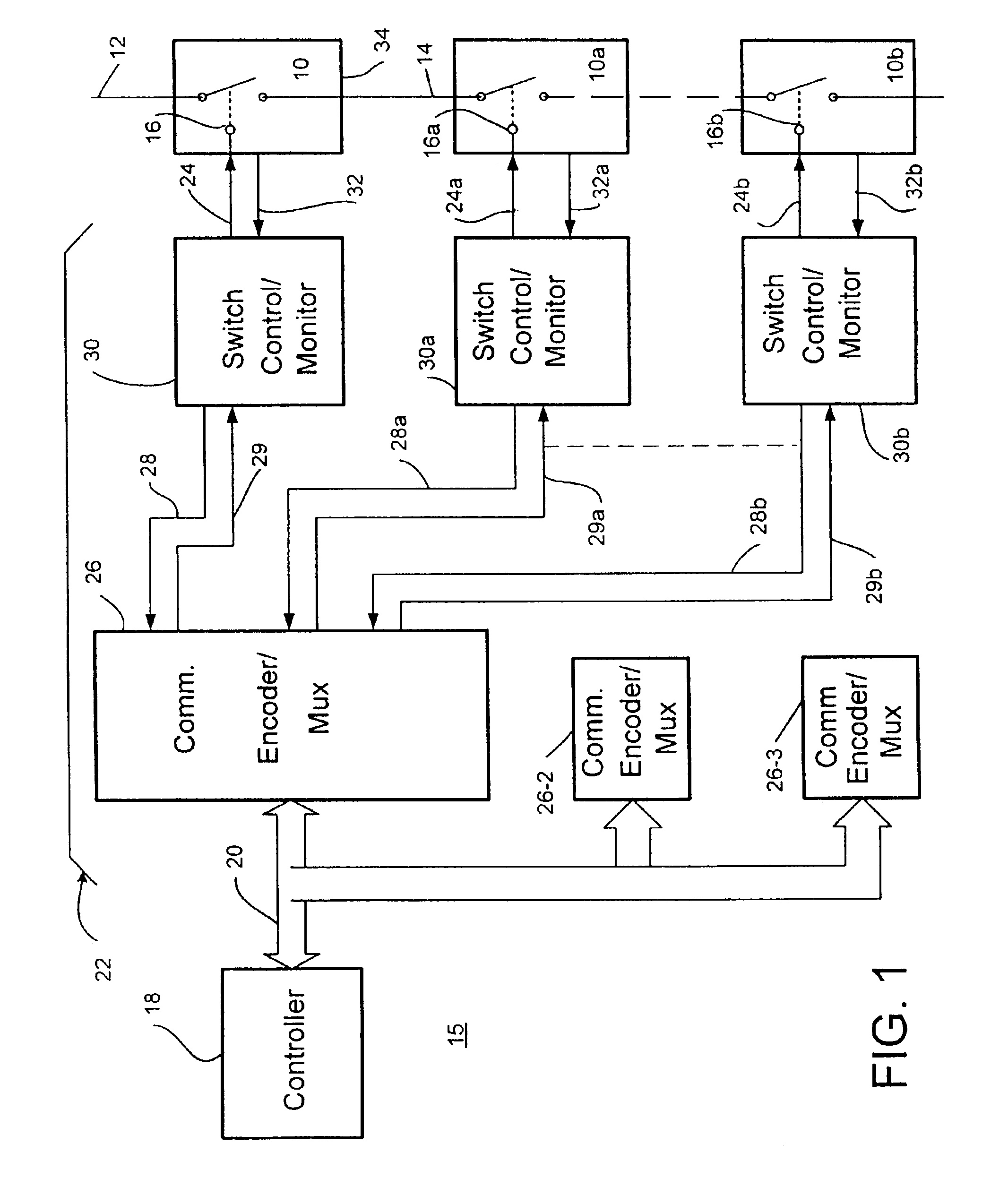
[0016]Referring now to FIG. 1, the control arrangement and method of the present invention will be described in connection with an illustrative system 15 that includes a controller 18 that monitors the condition and operating parameters of various components of the system 15 and takes appropriate action to optimize operation thereof, e.g. the operating characteristics of an illustrative electronic switch stage 10 are monitored as will be explained in more detail hereafter. As illustrated, the electronic switch stage 10 includes a main path between lines 12 and 14 that is controlled between on and off states, corresponding to respective conductive and nonconductive states, via a control connection at 16. In a specific illustrative example, the electronic switch stage 10 is a thyristor, IGBT, TRIAC, pair of inverse-parallel connected SCR's, or other actively controlled device.

[0017]The system 15 includes an illustrative communications arrangement 22 that cooperates with the controller...


PUM


Abstract

A control method and arrangement that monitors the condition and operating parameters of a power electronic system having power electronic devices and responds to various detected abnormalities to optimize operation of the power electronic system. The arrangement increases reliability of operation and optimizes the continuous supply of power to a load. The arrangement also includes the capability for diagnosing the parameters of the power electronic switches including drive current, drive voltage and operating temperature and for communicating the status information in a coordinated fashion.

Description

[0001]This application is a continuation-in-part application of application Ser. No. 10 / 192,441 filed on Jul. 11, 2002 in the names of Mikosz et al. now U.S. Pat. No. 6,667,601 (which in turn is a divisional application of application Ser. No. 09 / 556,259 filed on Apr. 24, 2000 now U.S. Pat. No. 6,504,696 based on Provisional application No. 60 / 131,724 filed on Apr. 30, 1999) and claims the benefit of U.S. Provisional Application Nos. 60 / 375,799 filed on Apr. 26, 2002 and 60 / 369,202 filed on Apr. 1, 2002.BACKGROUND OF THE INVENTION[0002]1. Field of the Invention[0003]The present invention relates generally to the field of power electronic systems and more particularly to control methods and arrangements that monitor the condition and operating parameters of the power electronic system and power electronic switches and provide appropriate action to optimize operation thereof.[0004]2. Description of Related Art[0005]Various power electronic systems are known for supplying power, regula...

Claims


Application Information

Patent Timeline
Patent Type & Authority Patents(United States)
IPC IPC(8): H02J3/00
CPCH02J3/005H02J3/007
Inventor KLIPPEL, TODD W.MIKOSZ, RICHARD P.ATANUS, RONALD D.ENNIS, MICHAEL G.O'LEARY, RAYMOND P.RUTA, JOSEPH W.MEARS, GREGORY C.
Owner S&C ELECTRIC
Why Eureka
Try Eureka