Display device

a display device and display technology, applied in static indicating devices, instruments, multi-frequency code systems, etc., can solve the problem of more expensive drive electronics, and achieve the effect of more expensiv

Inactive Publication Date: 2005-07-12
KONINKLIJKE PHILIPS ELECTRONICS NV
View PDF9 Cites 1 Cited by
  • Summary
  • Abstract
  • Description
  • Claims
  • Application Information

AI Technical Summary

Benefits of technology

[0008]It is found that orthogonal signals can thereby be generated which differ little in frequency content and thus do not give rise or hardly give rise to artefacts in the image. Such orthogonal signals are obtained, for example, from orthogonal functions having four elementary units of time, within which four elementary units of time the pulse having a polarity which differs from that of the other pulses each time shifts by one elementary unit of time. The u

Problems solved by technology

A larger number of column voltage levels to be used

Method used


Image

  • Display device
  • Display device
  • Display device

Examples


Embodiment Construction

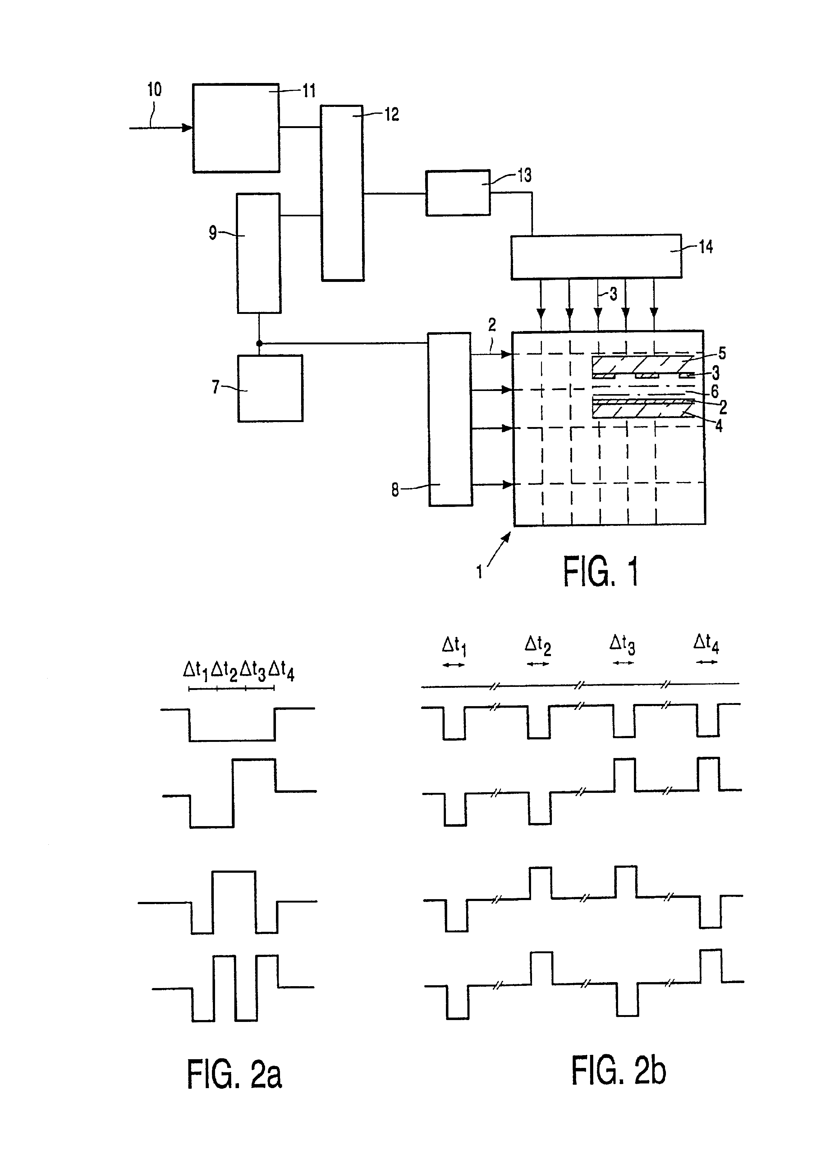
[0016]FIG. 1 shows a display device comprising a matrix 1 of pixels at the area of crossings of N rows 2 and M columns 3 which are provided as row and column electrodes on facing surfaces of substrates 4, 5, as can be seen in the cross-section shown in the matrix 1. The liquid crystal material 6 is present between the substrates. Other elements such as orientation layers, polarizers, etc. are omitted for the sake of simplicity in the cross-section.

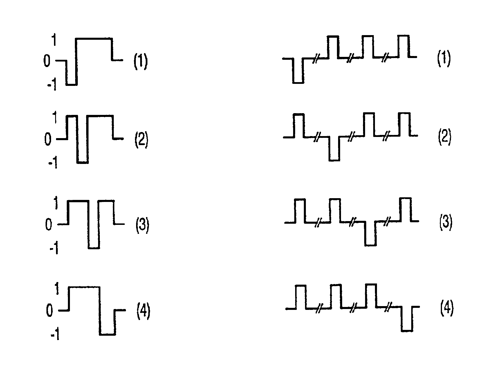
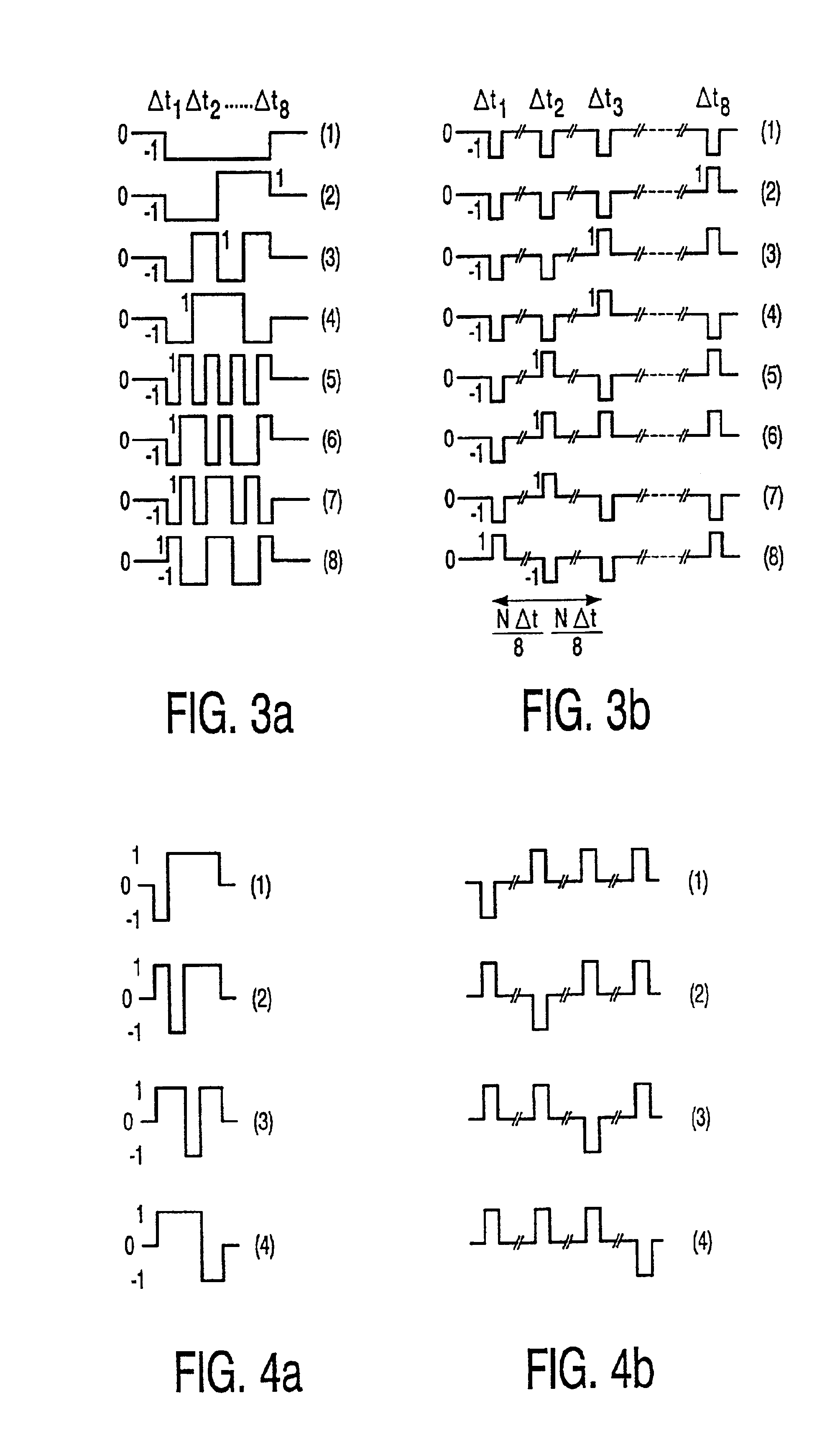
[0017]The device further comprises a row function generator 7 in the form of, for example, a ROM for generating orthogonal signals Fi(t) for driving the rows 2. Similarly as described in said article by Scheffer and Clifton, row vectors driving a group ofp rows via drive circuits 8 are defined during each elementary time interval. The row vectors are written into a row function register 9.

[0018]Information 10 to be displayed is stored in a pxM buffer memory 11 and read as information vectors per elementary unit of time. Signals for the col...


PUM


Abstract

A device for multiple row addressing is driven with pulse patterns based on sets of 8 (or more) orthogonal functions which have a less varying frequency content than pulse patterns based on a set of 8 Walsh functions. Mutually orthogonal signals are obtained from at least two types of the orthogonal functions having four elementary units of time. Within the four elementary units of time, one pulse each unit of time has a polarity which is different from the plurality of the other pulses.

Description

BACKGROUND OF THE INVENTION[0001]1. Field of the Invention[0002]The invention relates to a display device employing a liquid crystal material between a first substrate provided with row or selection electrodes and a second substrate provided with column or data electrodes, in which overlapping parts of the row and column electrodes define pixels. The display device further employs drivers for driving the column electrodes in conformity with an image to be displayed, and for driving the row electrodes which, in the operating condition, sequentially supply groups of p row electrodes with p mutually orthogonal signals. Such display devices are used in, for example, portable apparatuses such as laptop computers, notebook computers and telephones.[0003]2. Description of the Related Art[0004]Passive-matrix displays of this type are generally known and, for realizing a high number of lines, they are increasingly based on the STN (Super-Twisted Nematic) effect. An article by T.J. Scheffer a...

Claims


Application Information

Patent Timeline
IPC IPC(8): G09G3/36G09G3/20G02F1/133
CPCG09G3/3625G09G2310/06G02F1/133
Inventor KUIJK, KAREL ELBERT
Owner KONINKLIJKE PHILIPS ELECTRONICS NV
Why Eureka
Try Eureka