
Technique for verifying fiber connectivity in a photonic network

a technology of fiber connectivity and photonic network, which is applied in the direction of transmission monitoring, transmission monitoring/testing/fault measurement system, electrical equipment, etc., can solve the problems of laborious and time-consuming establishment of correct fiber connectivity, high labor intensity and labor-intensive photonic network commissioning,

Active Publication Date: 2005-07-12
CIENA
View PDF4 Cites 30 Cited by
  • Summary
  • Abstract
  • Description
  • Claims
  • Application Information

AI Technical Summary

Benefits of technology

[0016]In accordance with other aspects of this exemplary embodiment of the present invention, the messages are exchanged via an optical supervisory channel between the first node and the second node; one or more of the first node and the second node further comprises at least one light source for transmitting a light signal via the optical supervisory channel and at least one light detecting unit for detecting the light signal via the optical supervisory channel; the optical supervisory channel supports electro-optics functionality at one or more of the first node and the second node; and an alarm indicating a misconnection between the first node and the second node is activated when the intended port of the sec

Problems solved by technology

A great deal of time and effort is spent in the commissioning of a photonic network.
The commissioning of a photonic network is particularly difficult in a network installation phase, as photonic network elements are interconnected by dark fibers.
For example, a fiber link connected to port ‘1’ of a node A is to be connected to port ‘a’ of a distant node B. The problem that may arise is whether users at node A and node B can be sure that they have each selected the same fiber from a bundle of fibers, or whether they have connected the fibers to the assigned ports at either end.
Without a light source, establishment of correct fiber connectivity is labor intensive and time consuming.
If there is a fiber cut in that link, the user at the second end will not be able to detect a light signal from any fiber in the fiber bundle.
Thus, the user is not able to identify the correct fiber, or the user may select a wrong fiber from the fiber bundle.
The process required to correct this predicament is time consuming and labor intensive.
Therefore, the OSPF protocol does not provide information to confirm proper fiber connectivity.

Method used


Image

  • Technique for verifying fiber connectivity in a photonic network
  • Technique for verifying fiber connectivity in a photonic network
  • Technique for verifying fiber connectivity in a photonic network

Examples


Embodiment Construction

)

[0024]The present invention provides a measurement and test technique that utilizes an embedded OSC of a photonic network where associated functions of the OSC in each node support a variety of measurement and test functions for dark fibers in a photonic network.

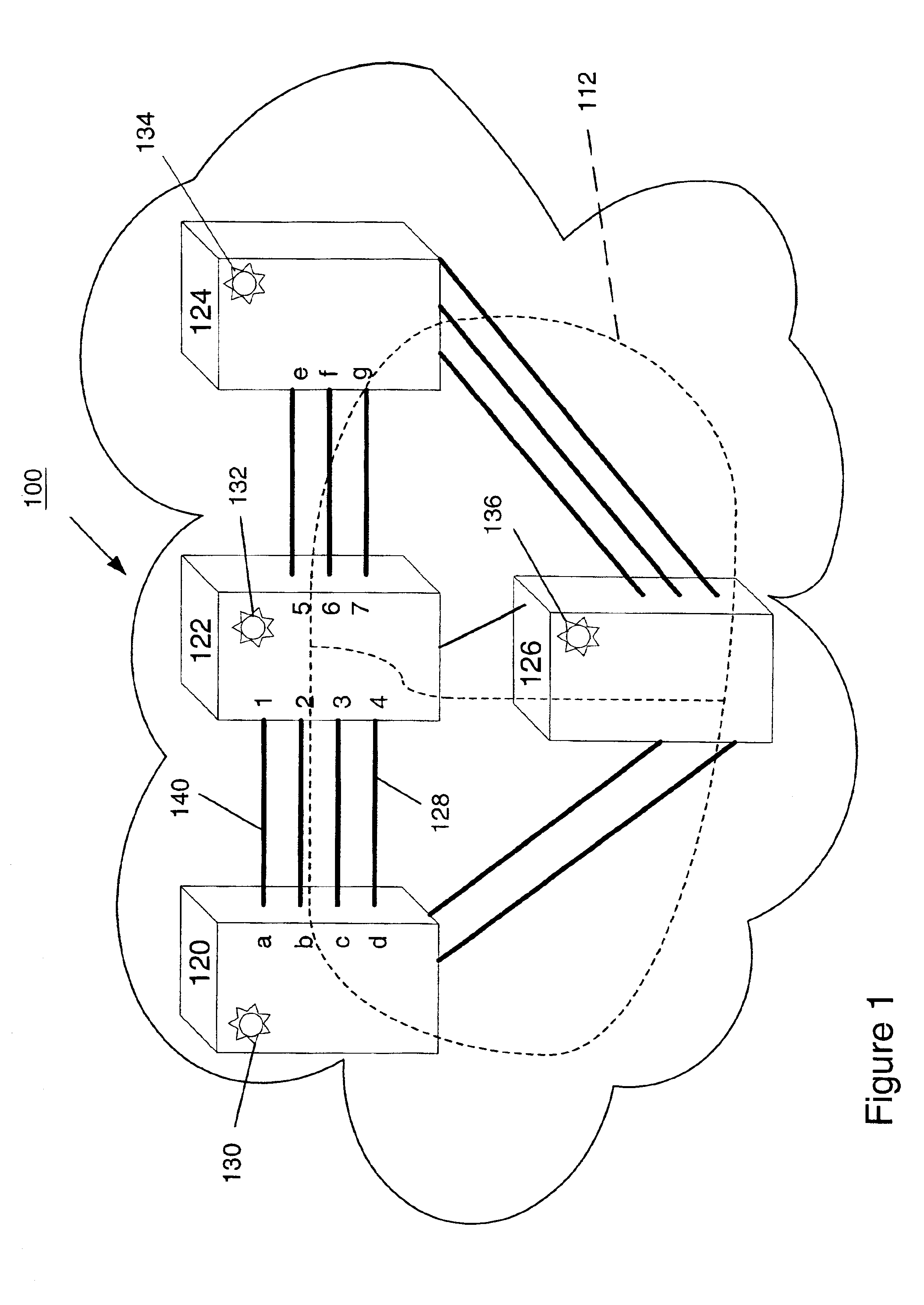
[0025]FIG. 1 is a photonic network 100 wherein fiber connectivity is verified in accordance with the present invention. The photonic network 100 comprises node 120, node 122, node 124 and node 126. At commissioning time, the nodes are interconnected with optical fibers, according to a specified plan. For example, port ‘a’ of node 120 is connected to port ‘1’ of node 122 to form an inter-nodal fiber link via optical fiber 140. Also, port ‘d’ of node 120 is connected to port 4 of node 122 to form an inter-nodal fiber link via optical fiber 128, which may be specified as a protection link. Fiber connections must be established as specified because the operation of the network is dependant on proper fiber connectivity. At commi...


PUM


Abstract

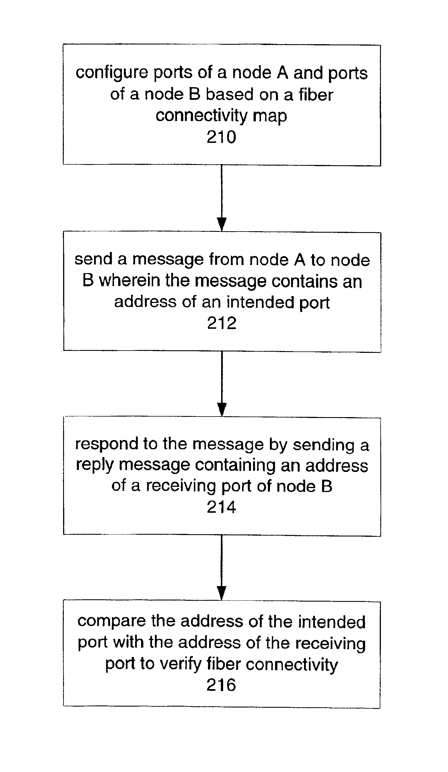
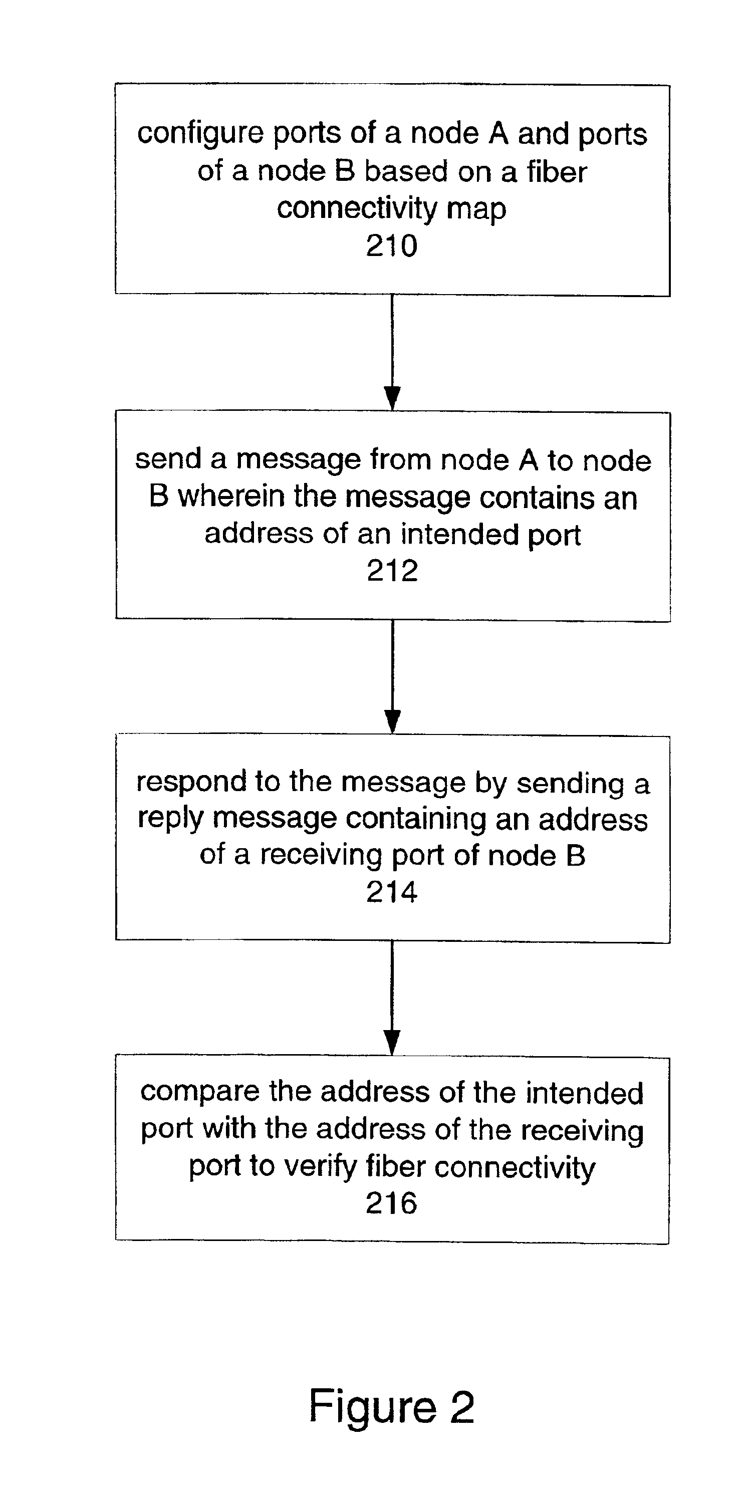
A technique for verifying fiber connectivity via an optical supervisory channel in a photonic network is disclosed. In one embodiment, the technique is realized by sending a first message from the first node to the second node, wherein the first message includes an address of an intended port of the second node; receiving a second message at the first node from the second node in response to the first message, wherein the second message contains an address of a receiving port of the second node; and comparing the intended port of the second node and the receiving port of the second node for verifying fiber connectivity between the first node and the second node.

Description

FIELD OF THE INVENTION[0001]The present invention relates generally to fiber connectivity verification and, more particularly, to a technique for verifying fiber connectivity via an optical supervisory channel in a photonic network.BACKGROUND OF THE INVENTION[0002]A photonic (or optical) network generally refers to a communications network in which information is transmitted entirely in the form of optical signals. A great deal of time and effort is spent in the commissioning of a photonic network. The commissioning of a photonic network is particularly difficult in a network installation phase, as photonic network elements are interconnected by dark fibers. A dark fiber is an optical fiber that is currently installed but not being used. Optical fibers convey information in the form of light pulses. Therefore, dark fibers imply that no light pulses are being sent.[0003]Generally, users (e.g., craft persons) follow instructions of network planners to interconnect nodes located approx...

Claims


Application Information

Patent Timeline
IPC IPC(8): H04B10/00H04B10/08H04B10/02
CPCH04B10/0771H04B2210/071H04B2210/078
Inventor AU, HOW KEEKUANG, RANDYWANG, GUO QIANG
Owner CIENA
Learn More