Data transmission method and data transmission apparatus

a data transmission and data technology, applied in the field of data transmission methods data transmission apparatuses, data receiving apparatuses, and packet data structures, can solve the problems of radio transmission quality, download type transmission methods are not suitable for long-hours of video data reproduction, and cannot perform data reproduction, so as to reduce the number of retransmission times, improve the transmission quality of radio sections in real-time transmission, and simplify the procedure

Inactive Publication Date: 2005-07-12
PANASONIC CORP
View PDF19 Cites 43 Cited by
  • Summary
  • Abstract
  • Description
  • Claims
  • Application Information

AI Technical Summary

Benefits of technology

[0014]The present invention is made to solve the above-described problems and has for its object to provide a data transmission method, a data transmission apparatus, and a data receiving apparatus, which can improve the transmission quality in a radio section in real-time transmission.

Problems solved by technology

So, the terminal cannot perform data reproduction until the file transmission is completed.
Therefore, the download type transmission method is not suitable for long-hours of reproduction of video data or the like.
However, the bit error rate in the radio transmission section is 10−3 while the bit error rate in the cable transmission section is 10−5˜10−7, and the radio transmission quality becomes a problem in the RTP type data transmission method in which the reproduction quality depends on the end-to-end (server-to-terminal) transmission quality.

Method used


Image

  • Data transmission method and data transmission apparatus
  • Data transmission method and data transmission apparatus
  • Data transmission method and data transmission apparatus

Examples


embodiment 1

[Embodiment 1]

[0092]FIGS. 1-3 are diagrams for explaining a data transmission method according to a first embodiment of the present invention.

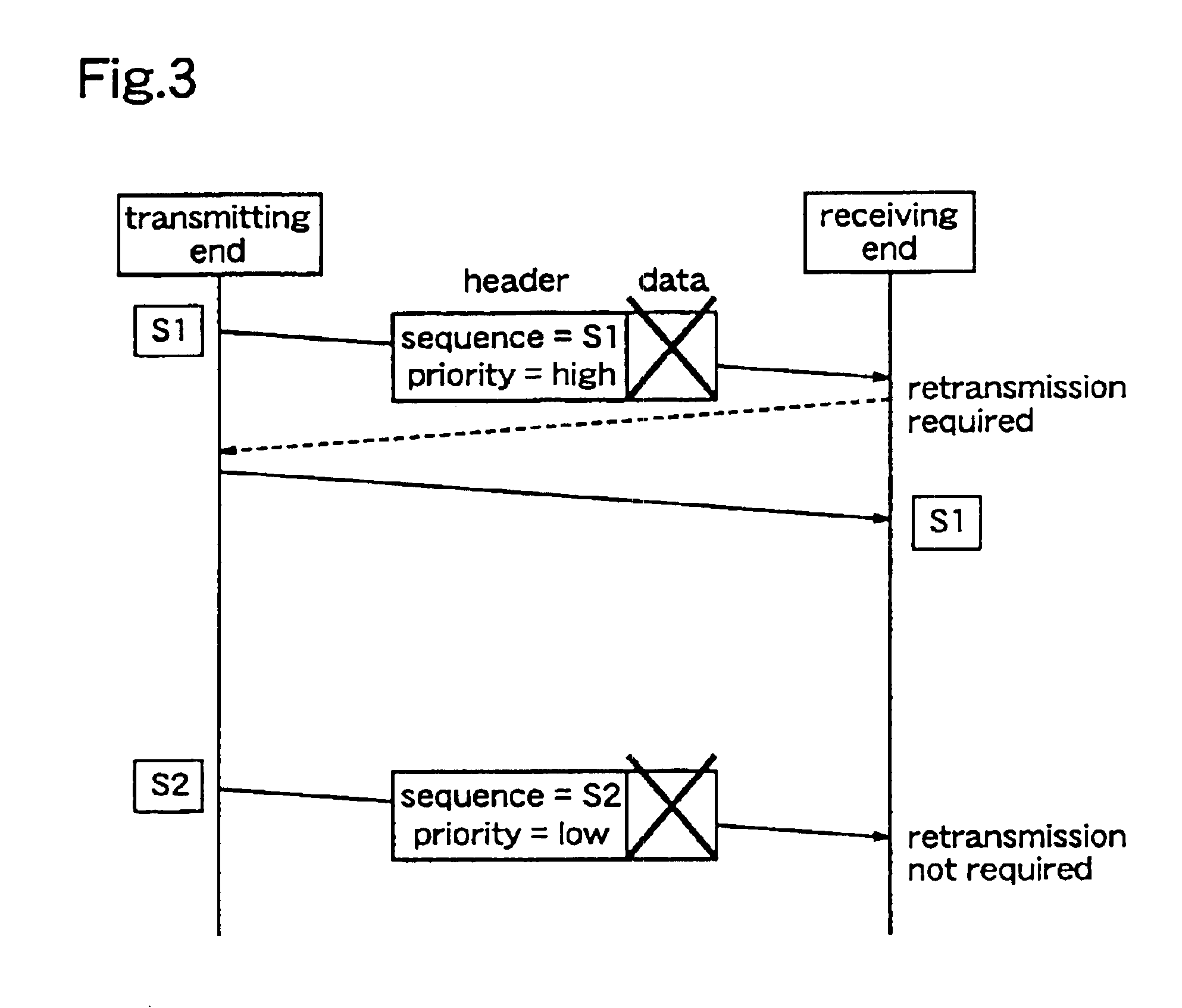
[0093]In the data transmission method of this first embodiment, data transmission from the transmitting end to the receiving end is continuously performed in units of packets, each packet having additional information relating to its sequence number, priority, and data reproduction time at the receiving end, while successively reproducing data of packets received at the receiving end. At this time, only error packets the priorities of which are equal to or higher than a predetermined value are retransmitted.

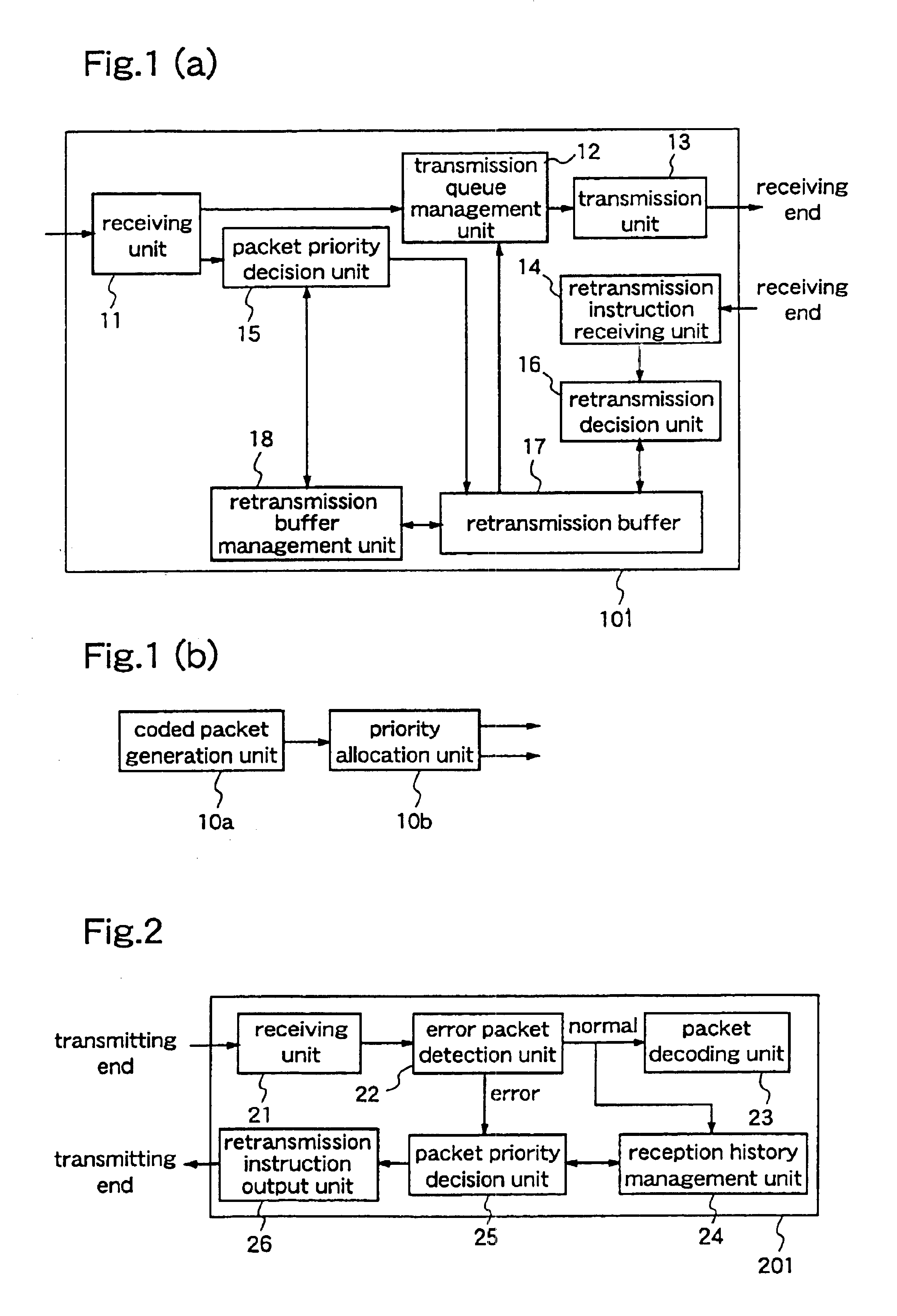
[0094]FIG. 1(a) is a block diagram illustrating a data transmission apparatus 101 in a data transmission system which performs real-time data transmission according to the data transmission method of the first embodiment.

[0095]This data transmission apparatus 101 constitutes a relay server (transmitting end) which relays data transmitted be...

embodiment 2

[Embodiment 2]

[0116]FIGS. 4-5 are diagrams for explaining a data transmission method according to a second embodiment of the present invention.

[0117]FIG. 4 is a block diagram illustrating a data transmission apparatus 102 in a data transmission system which performs real-time data transmission according to this data transmission method.

[0118]The data transmission apparatus 102 includes an error correction unit 31, in addition to the constituents of the data transmission apparatus 101 of the first embodiment. The error correction unit 31 performs an error correction process in which each packet output from the transmission queue management unit 12 is given error correction codes for additional information such as its sequence number priority, etc., and the packet which has been subjected to the error correction process is supplied to the transmission unit 13. Other constituents of the data transmission apparatus 102 are identical to those of the data transmission apparatus 101 of the...

embodiment 3

[Modification of Embodiment 3]

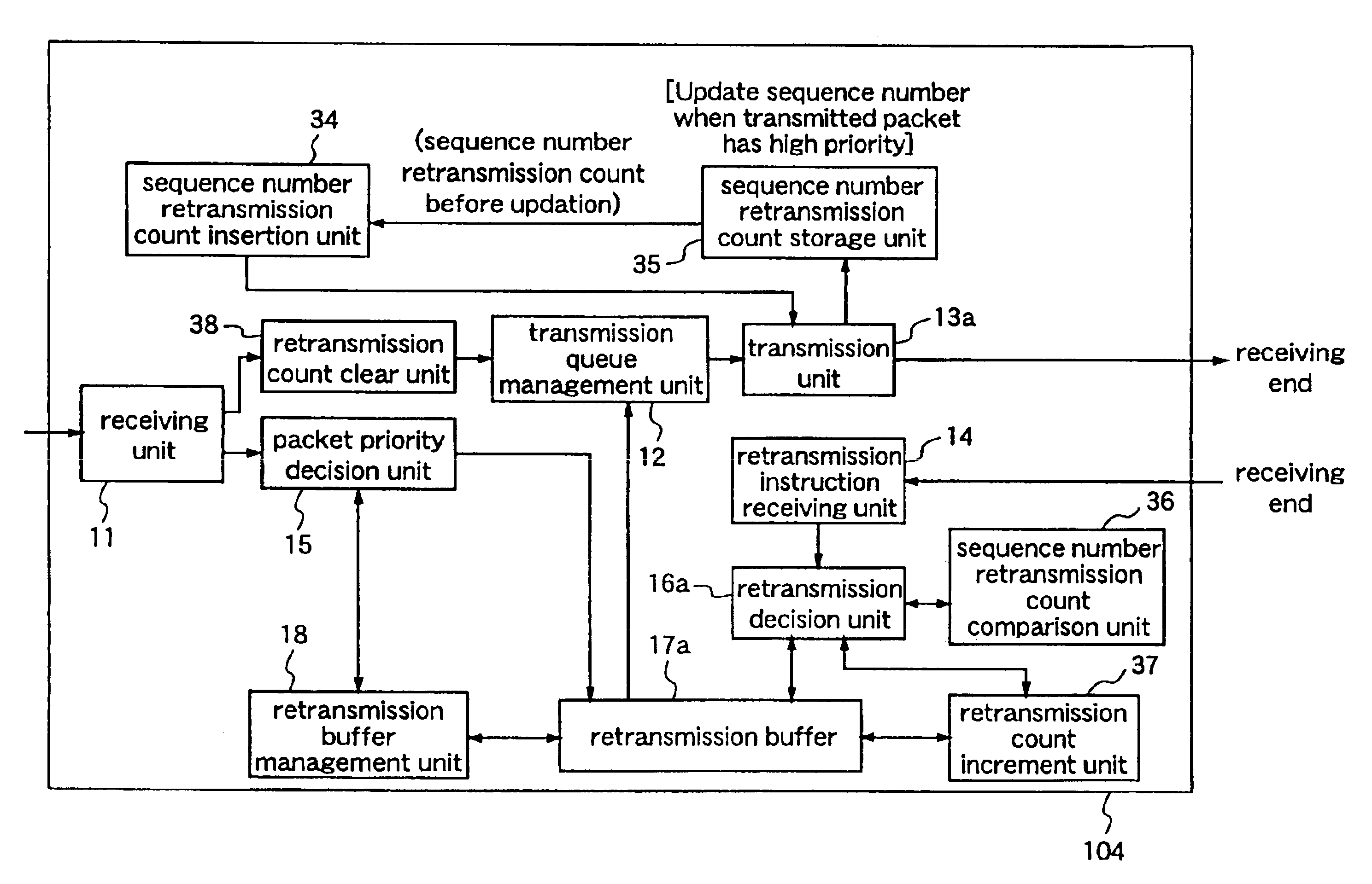
[0129]FIG. 7 is a block diagram illustrating a data transmission apparatus 103 in a data transmission system which performs real-time data transmission by using a data transmission method according to the modification of the third embodiment.

[0130]The data transmission apparatus 103 includes a sequence number storage unit 33 and a sequence number insertion unit 32, in addition to the constituents of the data transmission apparatus 101 of the first embodiment. The sequence number storage unit 33 stores the sequence numbers of the packets the priorities of which are equal to or higher than a predetermined value, amongst the packets transmitted by a transmission unit 13a. The sequence number insertion unit 32 outputs each of the sequence numbers stored in the sequence number storage unit 33 to the transmission unit 13a so that the sequence number is inserted in the header of the packet to be transmitted. Further, the transmission unit 13a of this modificat...


PUM


Abstract

A data transmission apparatus including a receiving unit for receiving transmitted packets; a priority decision unit; a retransmission packet storage unit; a retransmission instruction receiving unit for receiving a retransmission request from a terminal at the receiving end; a retransmission decision unit; a transmission queue management unit; and a transmission unit.

Description

[0001]This is a Rule 1.53(b) Divisional application of Ser. No. 10 / 227,456 filed Aug. 26, 2002 now U.S. Pat. No. 6,684,354, which is a Rule 1.53(b) Continuation application of Ser. No. 09 / 450,590, filed Nov. 30, 1999 now U.S. Pat. No. 6,587,985.FIELD OF THE INVENTION[0002]The present invention relates to data transmission methods data transmission apparatuses, data receiving apparatuses, and a packet data structure and, more particularly, to a process of performing data transmission in packet units between a distribution server and a terminal while successively reproducing the data of received packets at the terminal.BACKGROUND OF THE INVENTION[0003]For transmission of video (audio and video) data on the Internet, a download type transmission method and a stream type transmission method are currently employed.[0004]In the download type transmission method, a video file transmitted from a distribution server is once copied at the terminal and, thereafter, data of the video file (vide...

Claims


Application Information

Patent Timeline
Patent Type & Authority Patents(United States)
IPC IPC(8): H04L1/16H04L1/18H04L12/54H04N19/89
CPCH04L1/1642H04L1/1809H04L1/1854H04L1/1877H04L1/1887H04L1/1838H04L1/008
Inventor FUKUSHIMA, HIDEAKIHORII, SEIJIOHNISHI, TATSUYAHAGAI, MAKOTOMATSUI, YOSHINORIMIYAZAKI, AKIHIRO
Owner PANASONIC CORP
Why Eureka
Try Eureka