
Air conditioning system

a technology of air conditioning system and air conditioner, which is applied in the field of air conditioning system, can solve the problems of user discomfort, inability to maintain humidity, and polluted indoor air,

Inactive Publication Date: 2005-07-19
LG ELECTRONICS INC
View PDF12 Cites 42 Cited by
  • Summary
  • Abstract
  • Description
  • Claims
  • Application Information

AI Technical Summary

Benefits of technology

[0015]An object of the present invention is to provide an air conditioning system combining cooling, heating, ventilating, and dehumidifying functions.

Problems solved by technology

However, since the cooling / heating system is designed to cool and heat the indoor air and repeatedly circulate the cooled or heated air in the indoor space, the indoor air becomes polluted and the humidity of the air cannot be adjusted, causing the users to feel unpleasantness.
Furthermore, since the indoor air that has been heated or cooled to a predetermined temperature is exhausted to the outside, the changed indoor air must be cooled or heated to the predetermined temperature, causing an increase in energy consumption.

Method used


Image

  • Air conditioning system
  • Air conditioning system
  • Air conditioning system

Examples


Embodiment Construction

[0034]Reference will now be made in detail to the preferred embodiment of the present invention, examples of which are illustrated in the accompanying drawings. Wherever possible, the same reference numbers will be used throughout the drawings to refer to the same or like parts.

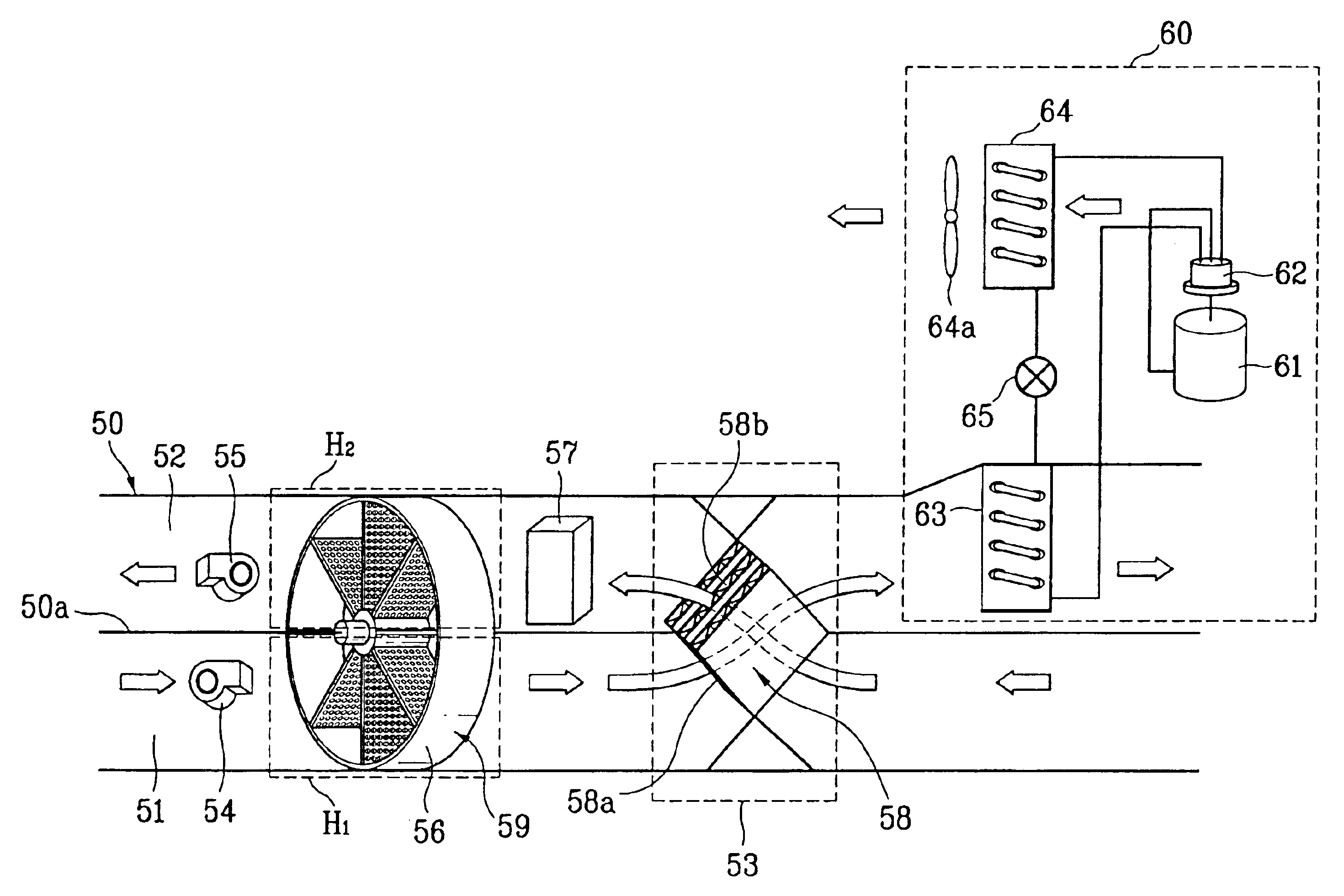
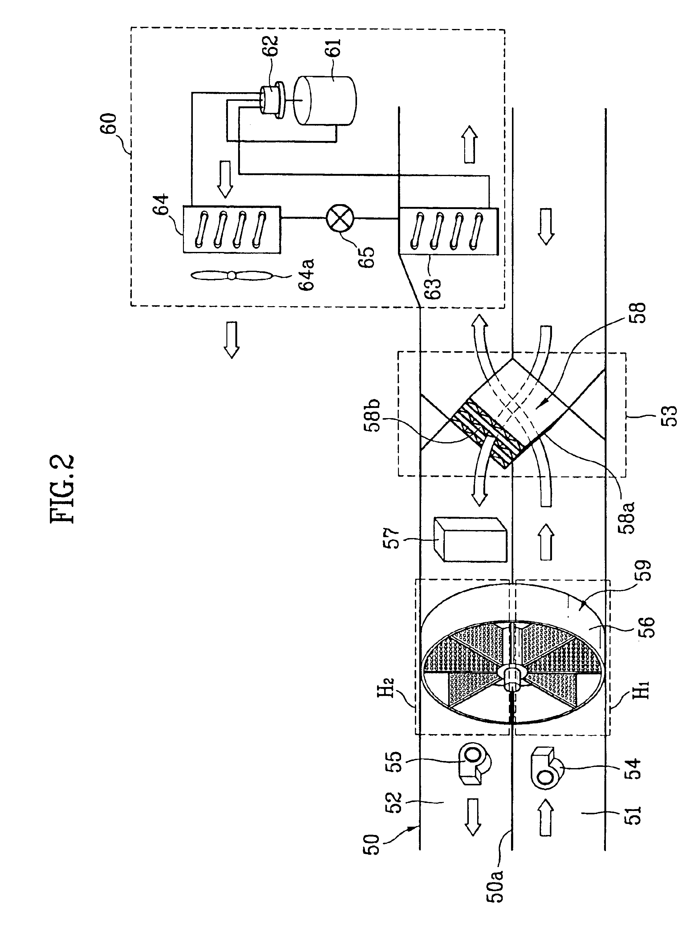
[0035]FIG. 2 shows an air conditioning system according to a preferred embodiment of the present invention, and FIG. 3 is a dehumidifying apparatus depicted in FIG. 2.

[0036]Referring first to FIG. 2, the inventive air conditioning system comprises a duct 50, a suction fan 54, a discharging fan 55, a dehumidifier apparatus 59, a regenerating heater 57, a regenerating heat exchanger 58, and a heat pump 60.

[0037]The duct 50 is provided with an air intake passage and an air discharge passage 52 that are separated from each other by a partition 50a. The suction fan 54 for suctioning outdoor air is installed in the air intake passage 51, and the discharge fan 55 for discharging indoor air is disposed in the dischar...


PUM


Abstract

Disclosed is an air conditioning system including a duct having an intake passage through which outdoor air is induced and a discharge passage through which indoor air is discharged, suction and discharging fans respectively installed in the intake and discharge passages, a dehumidifier having a desiccant wheel rotatably mounted on an opening of the partition, a regenerating heater for heating air induced into the dehumidifier, a regenerating heat exchanger provided on the intake and discharge passages in the vicinity of an indoor side with reference to the dehumidifier to heat-exchange air flowing along the intake passage with air flowing along the discharge passage, and a heat pump provided on the duct to heat-exchange outdoor air that has passed through the regenerating heat exchanger and discharging the heat-exchanged air to an indoor space.

Description

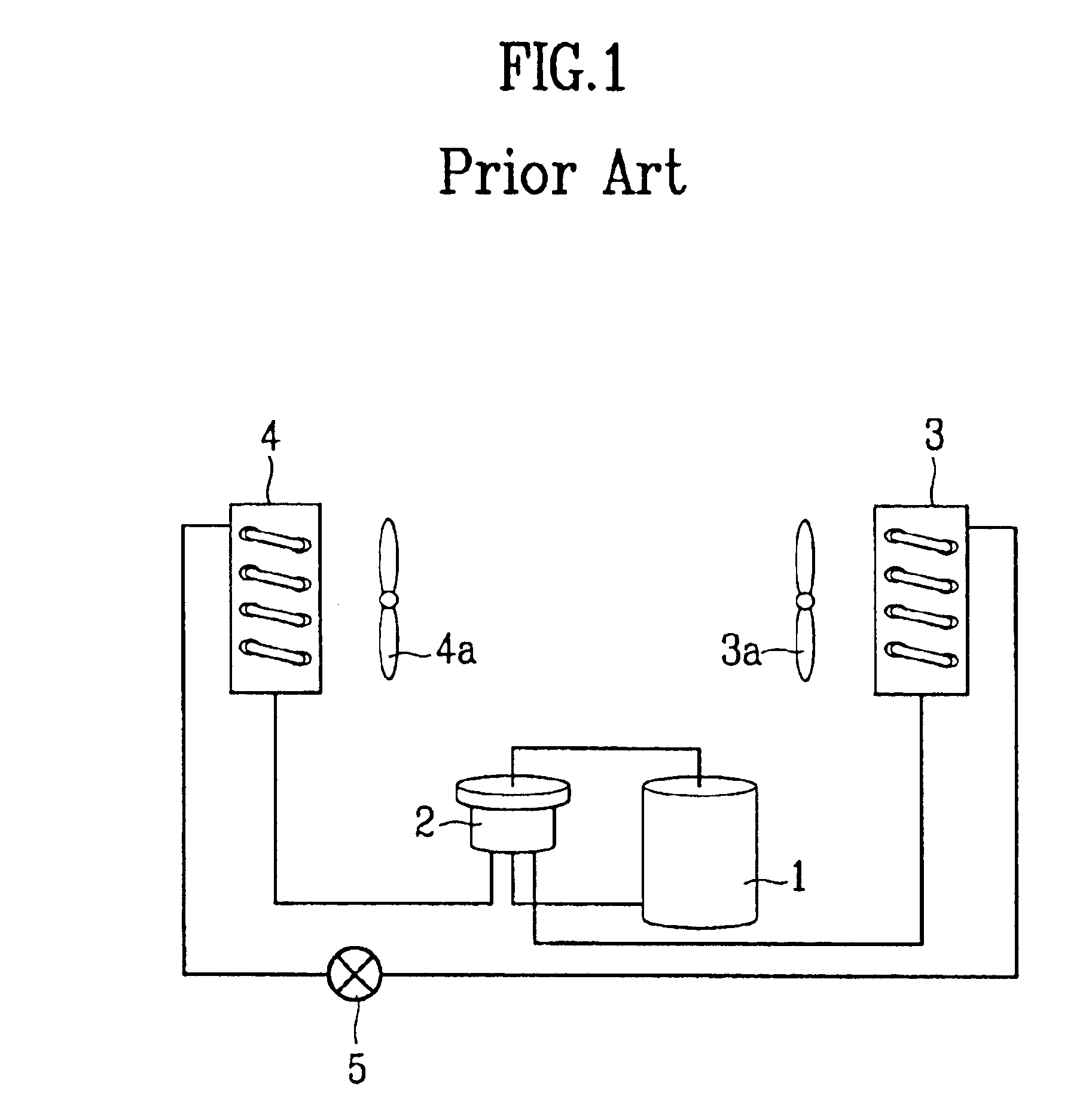
[0001]This application claims the benefit of the Korean Application No. P2002-0083915 filed on Dec. 26, 2002, which is hereby incorporated by reference.BACKGROUND OF THE INVENTION[0002]1. Field of the Invention[0003]The present invention relates to an air conditioning system, and more particularly, to an air conditioning system combining cooling, heating, ventilating, and dehumidifying functions.[0004]2. Discussion of the Related Art[0005]Generally, an air conditioner is an apparatus for providing a pleasant environment to an enclosed space such as a residential room, an office, and the like, by controlling the temperature and humidity of the space.[0006]FIG. 1 shows a cooling / heating system of a conventional air conditioner.[0007]As shown in the drawing, a cooling / heating system employed to a conventional air conditioner is configured to include a compressor 1, a four-way valve 2, an outdoor heat exchanger 3, an indoor heat exchanger 4, and an expansion apparatus 5. In the vicinity...

Claims


Application Information

Patent Timeline
Patent Type & Authority Patents(United States)
IPC IPC(8): F24F3/14F24F12/00F24F3/12F24F1/00F24F3/147F24F7/08F24F11/02
CPCF24F3/1423F24F12/006F24F2203/1016Y02B30/563F24F2203/1068F24F2203/108F24F2203/1084F24F2203/1032Y02B30/56F24F3/147
Inventor LEE, WON HEEHWANG, YOON JEISONG, CHAN HO
Owner LG ELECTRONICS INC
Learn More