Shift-by-wire transmission actuator assembly

a technology of transmission actuator and shift-by-wire, which is applied in the direction of gearing, manual control with single controlling member, mechanical control device, etc., can solve the problems of limiting the known shift-by-wire system, not providing manual override capability for transmission operation, etc., and achieves the effect of convenient attachmen

Inactive Publication Date: 2005-07-19
DUS OPERATING INC
View PDF16 Cites 64 Cited by
  • Summary
  • Abstract
  • Description
  • Claims
  • Application Information

AI Technical Summary

Benefits of technology

The invention is a transmission actuator that allows an automatic transmission to be operated in shift-by-wire mode during normal operation, and also provides a manual override mode that allows a driver to manually shift gears in the event of power loss or another event that disables the shift-by-wire mode. This actuator is small, efficient, and can easily be attached to current automatic transmissions. It eliminates the need for a battery backup for an electronic shift-by-wire actuator.

Problems solved by technology

The technical problem addressed in this patent is the lack of a manual override capability in shift-by-wire systems, which can make it difficult to operate the transmission in the event of a power loss or other emergency situations. The invention aims to provide a solution to this problem.

Method used


Image

  • Shift-by-wire transmission actuator assembly
  • Shift-by-wire transmission actuator assembly
  • Shift-by-wire transmission actuator assembly

Examples


Embodiment Construction

[0019]Although specific preferred embodiments of the actuator disclosed above are now described below, it should be understood that such embodiments are exemplary and serve to illustrate the principles disclosed. Various changes and modifications to the specific embodiments discussed below will become obvious to those skilled in the art in view of the present disclosure, and are deemed to be within the true spirit and scope of the invention as further defined in the appended claims.

[0020]In keeping with traditional patent usage, the terms “a,”“an,” and “the” are used here to mean, and should be understood to mean, “one or more” unless otherwise stated or a contrary meaning is made clear from the particular context. Thus, such terms include the singular and the plural.

[0021]It should be understood that directional terms used here refer to the direction shown in the drawings, unless otherwise clear from context.

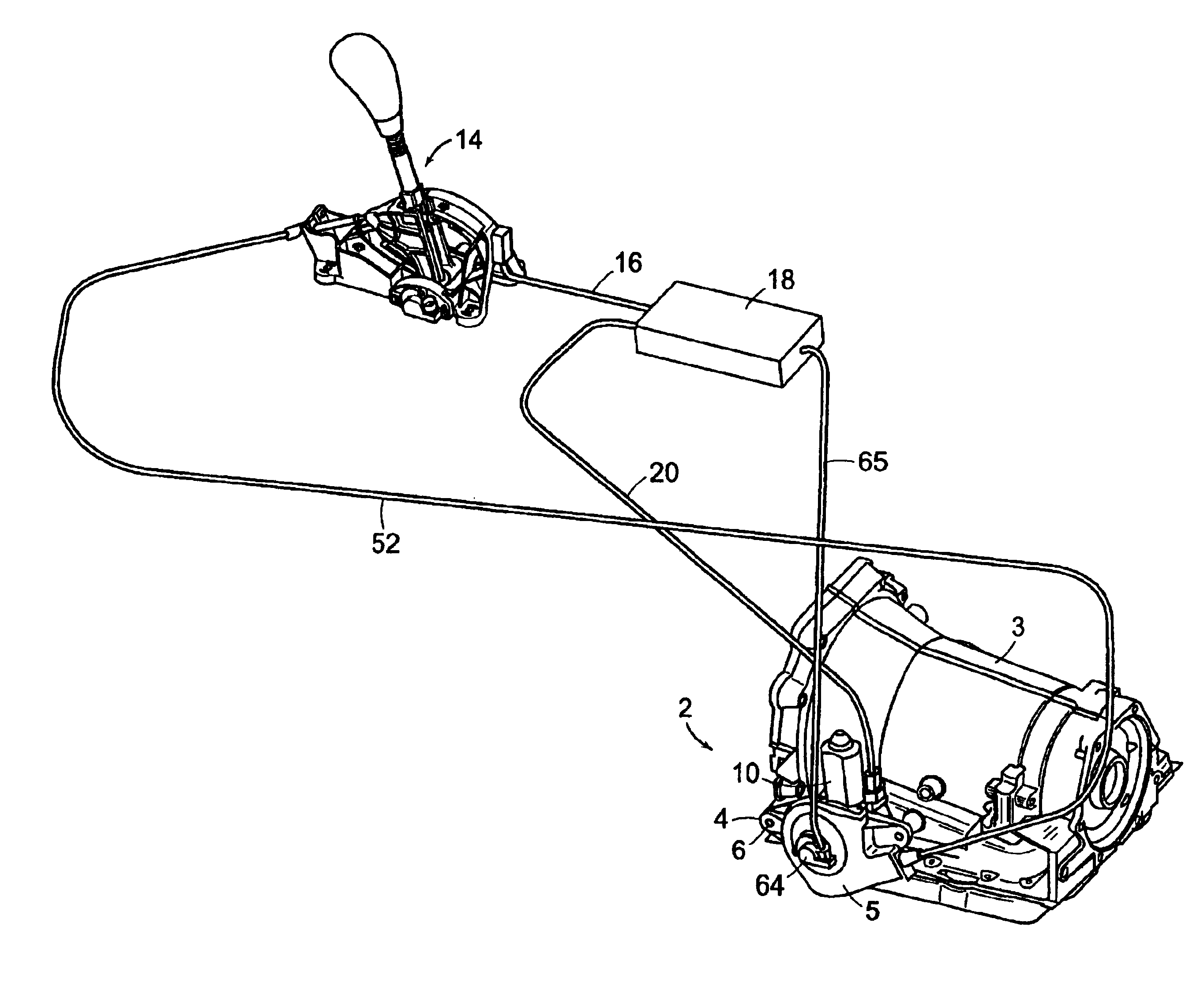
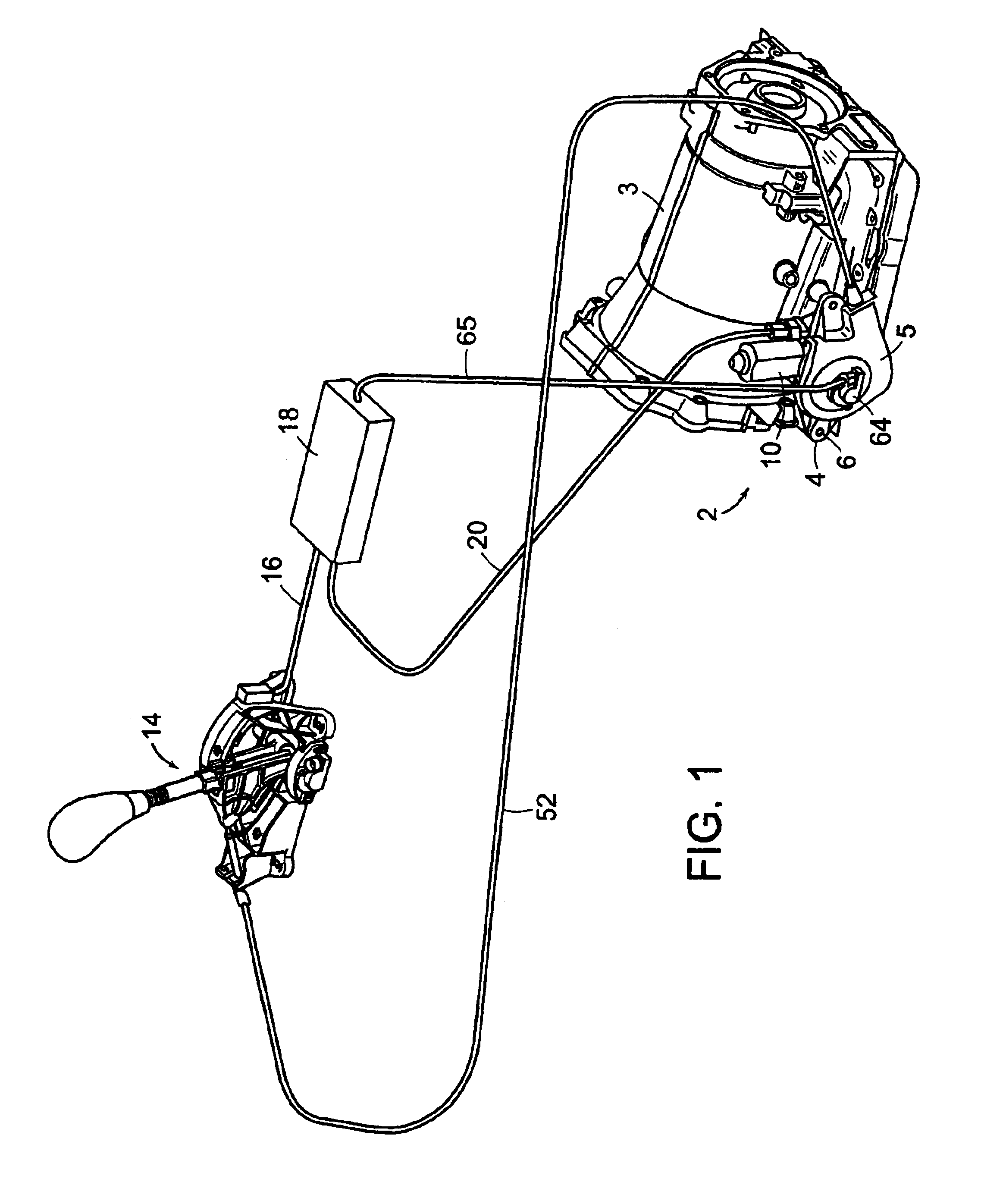
[0022]An actuator 2 for use with an automatic transmission 3 is shown in F...


PUM


Abstract

An actuator for a vehicle transmission having both a shift-by-wire mode and a manual override mode includes a motor and a gear assembly driven by the motor when the vehicle transmission is in a shift-by-wire mode. An output member of the gear assembly is configured to mate with the vehicle transmission. A release member is operable to drive the gear assembly when the vehicle transmission is in a manual override mode.

Description


Claims


Application Information

Patent Timeline
Owner DUS OPERATING INC
Why Eureka
Try Eureka